


The previous lesson showed you a detailed procedure of how to assign faces to a portion of a texture map, using the Edit UVWs dialog. In this lesson, you complete the mapping of the airplane, but the steps are less detailed, because for the most part, the methods are the same.
 open p47_texture_wing_left_top.max.
 click to select the P-47 fuselage, go to the
  Modify panel, then go to the Unwrap UVW modifier
  Face sub-object level.
Now you are ready to proceed with assigning more faces using Unwrap UVW.
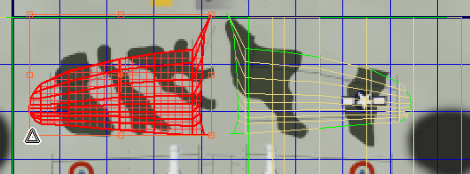
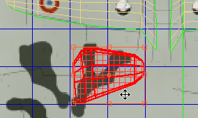
Map the top of the right wing:
Edit UVs rollout, click Open UV Editor.
 Crossing state, then in the Top viewport, drag a selection box to select all the faces on the top of the right wing.
In the Left viewport, Ctrl+click to select the narrow faces along the leading edge of the wing, as well.
Projection rollout, click  (Planar Map), then click
  (Align To Z), then click
  (Planar Map) once again to deactivate it.
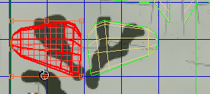
 Freeform Mode to rotate the wing 90 degrees counterclockwise, then move and scale the faces to position them over the camouflage
pattern to the left of the left wing pattern.
Freeform Mode to rotate the wing 90 degrees counterclockwise, then move and scale the faces to position them over the camouflage
pattern to the left of the left wing pattern.
 (Display Only Selected Faces), so you can match the size and proportion of the opposite side of the plane.
 Projection rollout, click (Planar Map), then click (Align To Z), then click (Planar Map) once again to deactivate it.
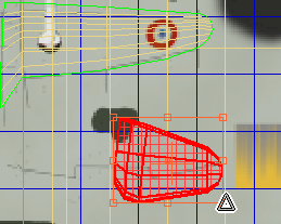
Freeform Mode to rotate the wing –90 degrees clockwise, then move and scale the faces to position them over the wing-bottom
pattern just below the left wing faces.
Projection rollout, click (Planar Map), then click (Align To Z), then click (Planar Map) once again to deactivate it.
Freeform Mode to rotate the wing –90 degrees clockwise, then move and scale the faces to position them over the wing-bottom
pattern just below the left wing faces. 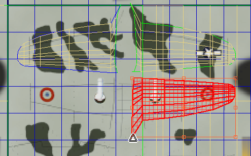
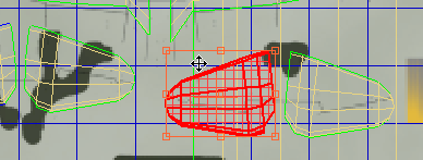
Map the horizontal stabilizers:
Because the fuselage is at an angle to the base of the horizontal stabilizers, you can’t select all of them with a single rectangle: Make an initial selection, then use Ctrl+click to add the remaining faces.
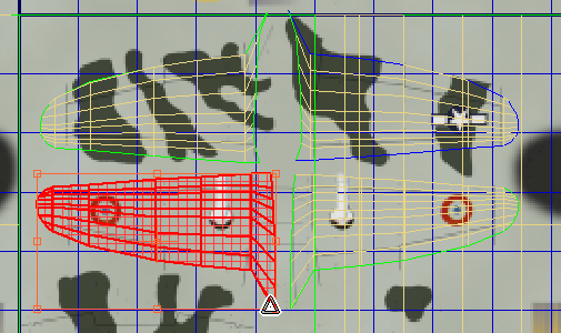
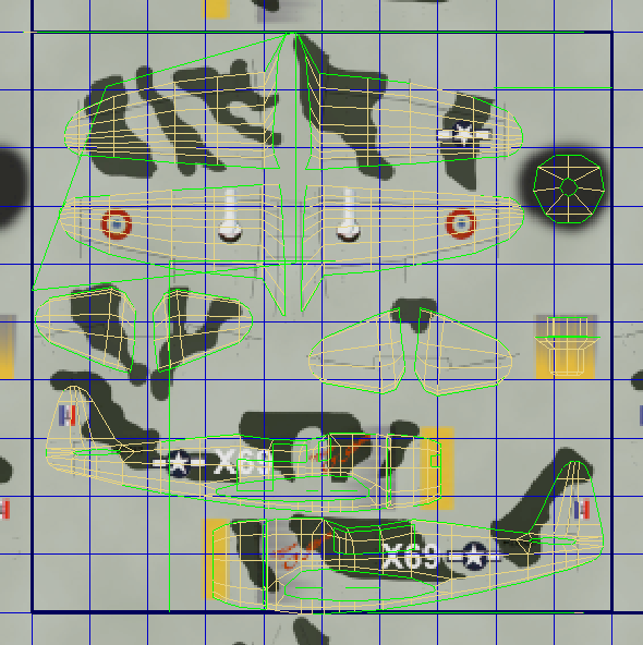
The pattern for the tops of the horizontal stabilizers is below the wings and to the left of the Edit UVWs window.
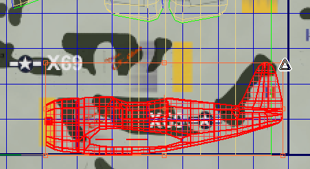
Top faces of the left horizontal stabilizer selected
(Planar Map), then click (Align To Z), then click (Planar Map) again to deactivate it.
 (Planar Map), then click (Align To Z), then click (Planar Map) again to deactivate it.
The pattern for the bottom of the stabilizers is also below the wings, but to the right.
(Planar Map), then click (Align To Z), then click (Planar Map) again to deactivate it.
 (Planar Map), then click (Align To Z), then click (Planar Map) again to deactivate it.
Map the sides of the fuselage:
 Paint Selection region to speed up the process. The green outlines displayed by the Unwrap UVW modifier are a good guide
to help you see which faces to include.
Paint Selection region to speed up the process. The green outlines displayed by the Unwrap UVW modifier are a good guide
to help you see which faces to include.
Pay particular attention to the narrow faces that surround the left wing and horizontal stabilizer; use both Top and Bottom views to make sure you select the narrow faces along the left-right seam.
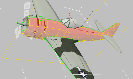
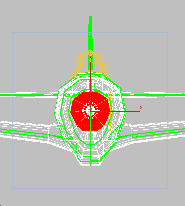
Camera001 viewport: Left side of the fuselage selected
In the Left viewport, Ctrl+click to add the faces on the leading edge of the engine cowl.
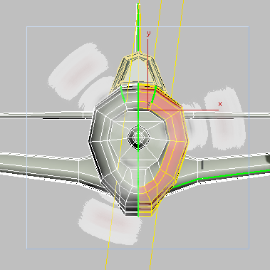
Left viewport: Front of engine cowl selected
(Planar Map), and then click  (Align To Y). Click (Planar Map) again to deactivate it.
 (Planar Map) to activate it, click (Align To Y), then click (Planar Map) again to turn it off.
 (Mirror Selected Subobjects) to orient the selection correctly, then in the Edit UVWs window, place the fuselage faces above
and to the left of the left-side selection.
(Mirror Selected Subobjects) to orient the selection correctly, then in the Edit UVWs window, place the fuselage faces above
and to the left of the left-side selection. 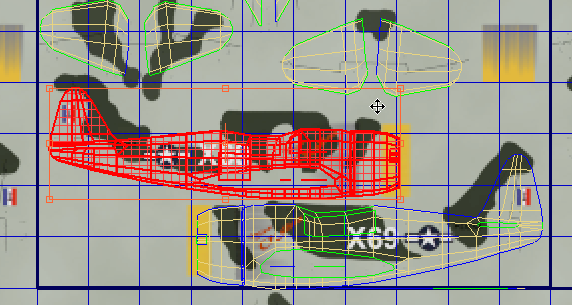
 (Planar Map), then click
  (Align To X). Click (Planar Map) a second time to deactivate it, then scale and move the faces so they are within the dark blob near the upper
right of the texture map.
(Align To X). Click (Planar Map) a second time to deactivate it, then scale and move the faces so they are within the dark blob near the upper
right of the texture map. 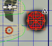
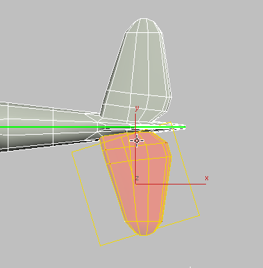
 Window state. In the Left viewport, drag to select the propellor shaft.
 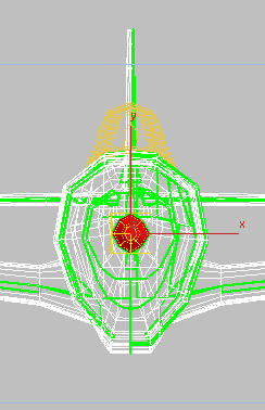 (Planar Map), then click (Align To Y). Click (Planar Map) a second time to deactivate it. Rotate the faces 90 degrees (counterclockwise), then scale and move the faces
so they are within the yellow and gray area below the air-intake faces.
(Planar Map), then click (Align To Y). Click (Planar Map) a second time to deactivate it. Rotate the faces 90 degrees (counterclockwise), then scale and move the faces
so they are within the yellow and gray area below the air-intake faces. 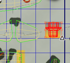
Now all the faces of the P-47 have been assigned the appropriate portion of the texture map.
 Close the Edit UVWs dialog.
 Render the Camera001 view.
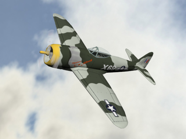
To see a completed version of this scene, you can open p47_texture_completed.max.
This tutorial showed how to apply a complicated texture, such as the painting of a military airplane, to 3ds Max geometry. To do so, use an Unwrap UVW modifier. At the modifier’s Face sub-object level, select the faces that correspond
to a portion of the map. Click (Planar Map) or  (Quick Planar Map) to generate an initial projection; then in the Edit UVWs dialog, use Move, Rotate, and Scale (or Freeform
Mode, which combines all three transforms) to place the selection over the portion of the map which has been designed for
those faces.
(Quick Planar Map) to generate an initial projection; then in the Edit UVWs dialog, use Move, Rotate, and Scale (or Freeform
Mode, which combines all three transforms) to place the selection over the portion of the map which has been designed for
those faces.
To create a patchwork texture such as the one used for the Thunderbolt, you can use the Viewport Canvas tool, which lets you interactively paint directly onto geometry. This How-To movie (part 1 of two parts) shows how to create a texture similar to the one used in the preceding tutorial.
 maximize the Left viewport (press
  orbit it so you can see the right side, make sure the narrow faces above the right wing are selected, and watch it while
you adjust how the faces are placed on the texture.
orbit it so you can see the right side, make sure the narrow faces above the right wing are selected, and watch it while
you adjust how the faces are placed on the texture.