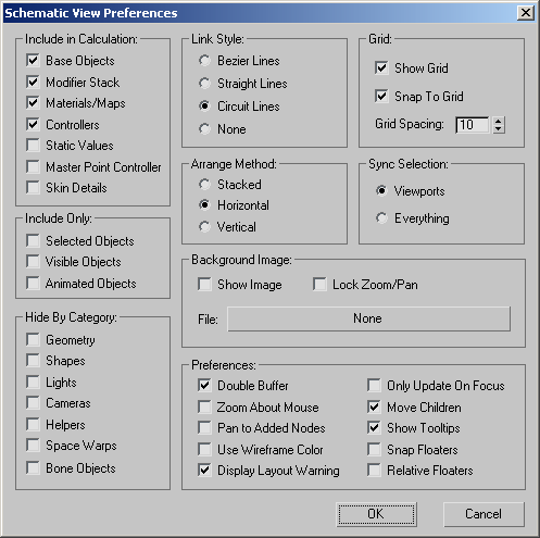
The Schematic View Preferences dialog controls what is shown and what is hidden based on categories. You can filter the objects
appearing in the Schematic View window, so you see only what you need to.
You can add a grid or background image into your Schematic View window. Here you can also choose the arrangement method and
determine the synchronization between viewport selection and Schematic view window selection. You can also set the style for
the node connections. By selecting the appropriate filters in this dialog you can make working with Schematic View more controllable.
Interface
Include in Calculation group
Schematic View can traverse the entire scene, including materials, maps, controllers, and so on. The Include In Calculation
settings control which scene components Schematic View will know about. The Display Floater then controls what is displayed.
So, if you don’t Include Materials, you can’t display materials. If you don’t include controllers, you can't display controllers,
constraints, or parameter-wiring relationships.
If you have a huge scene and are interested only in using Schematic View for selection, you can turn everything off except
Base Objects. If you are interested only in materials, you can turn off controllers, modifiers, and so on.
- Base Objects
-
Turns on and off the display of the base objects. Use this to remove clutter in the Schematic View window.
- Modifier Stack
-
Turns on and off the display of modifier nodes.
- Materials/Maps
-
Turns on and off the display of material nodes in the Schematic View window. Hide the materials when you are animating and
don’t need to see them, display them when you want to select materials or make changes to the material of various objects.
NoteSchematic View does not support the ability to manipulate maps. You can not paste a map from one material to another.
- Controllers
-
When this is turned on, controller data is included in the display. When this is turned off Controllers, Constraints and Param
Wires relationship and entity buttons are unavailable in the Display floater. When this is on, you can assign controllers
or wire parameters using the tools quad of the Schematic View right-click menu.
- Static Values
-
When this is turned on, unanimated scene parameters are included in the Schematic View display. Turn this off to prevent the
window from filling up with everything seen in Track View.
- Master Point Controller
-
When this is on, sub-object animation controllers are included in the Schematic View display. This button prevents the window
from filling up with too many controllers in cases in which sub–object animation is present.
- Skin Details
-
When this is turned on four controllers for each bone in the Skin modifier are included in the Schematic View display (when
Modifiers and Controllers are also included). This button prevents the window from stretching out around too many Skin controllers
with normal use of the Skin modifier.
Include Only group
- Selected Objects
-
Filters the display of selected objects. Check this box if you have a lot of objects and only want Schematic View to display
the viewport selection.
- Visible Objects
-
Limits the display in Schematic View to the visible objects. Hide objects you don’t need to display, then check this box to
contain clutter in Schematic View.
- Animated Objects
-
When this is turned on, then only objects that have keys and their parents will be included in the Schematic View display.
Hide By Category group
These toggles control the display of objects and their children, by category. The categories are:
- Hides or displays geometric objects and their children.
- Hides or displays shape objects and their children.
- Hides or displays lights and their children.
- Hides or displays cameras and their children.
- Hides or displays helper objects and their children.
- Hides or displays space warp objects and their children.
- Hides or displays bone objects and their children.
Be aware that if you have a hierarchy linked to a helper such as a dummy, and you hide the dummy, you’ll also hide the children.
Link Style group
- Bezier Lines
-
Displays the reference lines with arrowheads as Bezier curves.
- Straight Lines
-
Displays the reference lines as straight lines instead of Bezier curves.
- Circuit Lines
-
Displays the reference lines as orthogonal lines instead of curves.
- None
-
When this is chosen, link relationships will not appear in the Schematic View display.
Grid group
This group controls the display and use of a grid in the Schematic View.
- Show Grid
-
Displays a grid in the background of the Schematic View window.
- Snap to Grid
-
When this is on, all moved entities and children of those entities will snap their upper left corners to the nearest grid
point. Entities not snapped to a grid point when snap is enabled will not snap until they are subsequently moved.
- Grid Spacing:
-
Sets the spacing units of the Schematic View grid. This uses the standard that entities are 20 grid units high and 100 grid
units long.
Arrange Method group
Arranging always takes place within the confines of the positive X and negative Y space which is delineated by the darker
grid lines.
- Stacked
-
When this is turned on, arranging via Always Arrange, Arrange Children or Arrange Selected will result in the hierarchies
being stacked below a width that is determined by the extents of the highest entities in the view.
- Horizontal
-
When this is turned on arranging using Always Arrange, Arrange Children or Arrange Selected will result in the hierarchies
being distributed along and below the y=0 line. Arranging always takes place within the confines of the positive X and negative
Y space.
- Vertical
-
When this is turned on arranging using Always Arrange, Arrange Children or Arrange Selected will result in the hierarchies
being distributed along and to the right of the x=0 line. Arranging always takes place within the confines of the positive
X and negative Y space.
Sync Selection group
- Viewports
-
When this is chosen, node entities selected in Schematic View will have their corresponding nodes selected in the viewports.
Likewise, nodes selected in the viewports will have their corresponding entities selected in Schematic View.
- Everything
-
When this is chosen, all entities selected in Schematic View will have their corresponding entities selected in the appropriate
places in the interface, given that those places are open. For instance, selecting a material in Schematic View will select
it in the material editor if it is open and the material is present, selecting a modifier in Schematic View will select it
in the stack is the Modify panel is open. Likewise, entities selected in the scene will have their corresponding entities
selected in Schematic View.
- None
-
When this is chosen, changes in the viewport selection do not affect the Schematic View display, and selection changes in
the Schematic View display do not affect the viewport selection.
Background Image group
- Show Image
-
When on, the background bitmap (if one is chosen) is displayed. When off, it is not displayed.
By default, the background image displays at screen resolution at the current zoom factor of Schematic View.
- Lock Zoom/Pan
-
When this is turned on, zooming and panning resizes the background image accordingly. When turned off, the bitmap will remain
or revert to actual pixels at screen resolution.
- File button
-
Click to choose an image file for the background of Schematic View.
When no background image has been chosen, this button displays “None.” If an image has been chosen, it shows the name of the
bitmap file.
Preferences group
- Double Buffer
-
Allows for double buffer display to control viewport performance.
- Zoom About Mouse Pointer
-
When this is turned on you can zoom into wherever you place your cursor. You can also zoom with the zoom wheel, or hold Ctrl and press the middle mouse button.
- Pan to Added Nodes
-
When this is turned on the Schematic View window will alter itself to accommodate new objects or nodes as they are added to
the scene. When this is turned off the view is unchanged. Leave this off and turn off Auto arrange, and Schematic view will
not disturb the layout of the nodes.
- Use Wireframe Color
-
Uses the wireframe color to shade the node in the Schematic View window.
- Display Layout Warning
-
When this is on, Schematic View will show a layout warning when Always Arrange is first turned on.
- Only Update On Focus
-
When this is turned on, Schematic View only updates with additions or changes to the scene when it is given focus. This lets
you avoid constant redraws when making changes in the viewport to the scene objects.
- Move Children
-
When this is turned off you can move the parent without affecting the children. When this is turned on, moving a parent also
moves the children.
- Show Tooltips
-
Toggles the display of tooltips when the cursor is over the node in the Schematic View window.
- Snap Floaters
-
Enables floating dialogs (Display and List) to snap to the edges of the Schematic View window.
- Relative Floaters
-
Enables floating dialogs to move and resize as the Schematic View window is moved and resized.