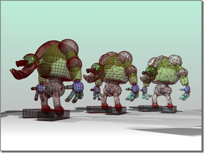
The MultiRes modifier reduces the memory overhead needed to render models by decreasing the number of vertices and polygons. This is useful not only within 3ds Max, but for content creators who export models for use outside of 3ds Max, such as in Web-based 3D applications. MultiRes offers several advantages over the Optimize modifier, including faster operation and the ability to specify reduction as an exact percentage or vertex count.
The MultiRes modifier preserves map channels when you use it to optimize a mesh.

Left: Original model
Center and right: Model progressively simplified by the MultiRes modifier
The MultiRes multi-resolution mesh algorithms are designed to be general-purpose, and yield high-quality meshes on a wide variety of model types. However, careful modeling can improve the results of the algorithm. The following are suggestions to yield high-quality multi-resolution meshes:
 Select a model and
  apply the MultiRes modifier.
As the vertex and polygon counts decrease, the mesh updates in real time in the viewports.
To maintain part of a mesh at full resolution while reducing the rest:
 Select a model and apply the MultiRes modifier.
 modifier stack, click
  (the plus-sign icon) next to the MultiRes modifier to open the sub-object hierarchy.
 Select the vertices in areas whose resolution you want to maintain.
Notice that the selected vertices look like asterisks instead of standard ticks.
The selected vertices are the last to be removed during vertex reduction.
If there are gaps between vertices that you want to close as vertex resolution decreases, use the Vertex Merging feature of the MultiRes modifier. With vertex merging, vertices within a given threshold distance eventually collapse during vertex reduction.
You can estimate the gap length by activating the Select Object tool, moving the mouse cursor over the extents of the gap in the active viewport (it might help to access the Vertex sub-object level), and comparing the values displayed in the X/Y/Z readouts in the status bar, or use the Tape helper object to get an exact measurement. Enter the estimated gap length value in the Threshold field.
 Select a model and
  apply the MultiRes modifier.
The effect of the change is displayed in the object.
After the Generate button is clicked, a busy cursor will display. If the merge threshold is too large relative to the dimensions of the model, the busy cursor may display for a long time. To cancel the generation process at any time, press the Esc key.

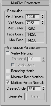
Use these controls to change the vertex count and overall topology of the modified object.
The modified object's vertex count as a percentage of the overall number of vertices in the original mesh. Adjusting this setting alters the Vert Count value as well.
When on, lets MultiRes merge vertices between discrete elements in a model.
For example, if you apply MultiRes to a teapot, which comprises four separate elements, and turn on Vertex Merging, as you adjust the vertex resolution, the separate components will meld together into one contiguous lower-resolution object.
To control Vertex Merging, you can set a Merge Threshold. This value determines the unit distance within which vertices will merge at a higher rate.
When on, MultiRes merges the boundaries of adjacent elements and vertices within elements. Many objects can contain multiple groups of vertices that don't share connectivity. A simple example of this is the Teapot object. It comprises four different elements: the body, the handle, the spout, and the lid. Normally, MultiRes optimizes each discrete element in a mesh on its own.
The default behavior of the Vertex Merging option is to merge vertices between elements. Turning on Within Mesh causes vertices within elements to be merged as well.
When on, overrides the MultiRes optimization algorithms and preserves any vertices selected at the MultiRes Vertex sub-object level as "critical" ones. Use this feature to retain critical features of an object or character such as its fingers or claws, or other geometry that might become unrecognizable if reduced too severely.
To select vertices for use with this option, use the MultiRes Vertex sub-object level. To access this level, first go to the modifier stack display and click the plus-sign icon next to the MultiRes modifier. This opens its hierarchy, which consists of the single Vertex sub-object level. Next, click the Vertex entry. The MultiRes vertices appear on the mesh as blue dots. You can select these using any standard interactive method, but you cannot transform them.
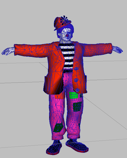
In the following illustration, the clown started out as a high-resolution mesh. All of the MultiRes vertices in the right half were selected, Maintain Base Vertices was turned on, and then the vertices were reduced.

Clown model with left half reduced, right half at original resolution
When on, MultiRes can assign multiple normals for each vertex. By default, MultiRes generates a single normal per vertex.
If multiple normals are generated, they are applied dynamically as the vertex resolution changes.
When the Multiple Vertex Normals option is on, the MultiRes modifier generates normal updates when the geometry surrounding a vertex changes. You must specify a crease angle in degrees (0.0 - 180.0). The crease angle is the angle between the face normals. It is used to decide when a normal should be shared across an edge between two faces.
For example, in a plane defined as a mesh grid of 10 x 10 faces, any two adjacent faces have a crease angle of zero. In a cube, adjacent faces have a crease angle of 90 degrees. In general, crease angles approaching 0 yield smoother shading. Crease angles approaching 180 yield more visible corners.
The value of the crease necessary in order to generate multiple normals. Available only when Multiple Normals Per Vertex is on.
The optimal crease angle depends on the model; set it interactively and check the viewport and rendered images for shading effects. While use of Multiple Vertex Normals enables more accurate shading, it can require more internal data.