Sliding and Rotational Joints (HI Solver)


Command entry:Create a bone chain. Apply an HI Solver Select any bone in the chain. Open the Hierarchy panel. IK button

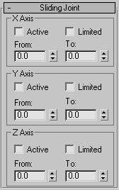
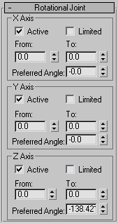
Here are the controls for setting the joint limits when using the HI Solver. You can turn X, Y, or Z axes on or off, limit them, and set those limits here. This is also where the preferred angle is defined, and adjusted. The preferred angle defines the direction a chain will bend, which angle a chain will tend to rotate toward.

NoteSliding joints are implemented in the HI Solver, but they do not take part in an IK solution. They do, however, take part during FK interactive manipulation.

Use the HD Solver if you need to animate sliding joints with inverse kinematics.

Procedures

Example: To set the direction an IK chain will bend (preferred angle):

To understand setting the preferred angle it helps to use a simple example.

  1. Go to the Create panel, click (Systems) and turn on Bones.
  2. Turn on Assign To Children and make sure the HI Solver is displayed in the Solver name field.
  3. In the Top viewport, create a bone chain of four bones in a straight line .
  4. Turn on (Auto Key), and drag the time slider to frame 50.
  5. Move the goal so it is close to the root node.
  6. Select any bone in the chain.
  7. On the Hierarchy panel IK panel, open the Rotational Joint rollout.
  8. There are three axes. Find the one with the preferred angle that is not zero.
  9. Change the preferred angle. If it is negative make it a positive one.
  10. Play the animation. Changing the preferred angle can redefine the direction of the rotation.

To set rotational joint limits on a hierarchy of objects or a bone chain:

  1. Create a bone chain or a hierarchy of objects.
  2. Select any object in the chain.
  3. On the Hierarchy panel IK panel, open the Rotational Joint rollout.
  4. If you want to limit an axis, turn on Active and Limited, and set the values of From and To. The hierarchy will rotate in the viewport.
    TipPressing the From and To labels instantly rotates the bone to those angles.

Interface

Sliding Joints rollout

X, Y, Z Axis groups

Active

Activates an axis (X/Y/Z). Allows the selected object to slide on the activated axis.

Limited

Limits the range of motion allowed on an active axis. Use in conjunction with the From and To spinners. Most joints are limited in their range of motion along an active axis. For example, a piston slides only within the length of its cylinder.

From and To spinners

Determine for position limits. Use in conjunction with the Limited function. Clicking the labels From and To moves the object to its limit position. Use this to check the sliding limits on an object.

Rotational Joints rollout

X, Y, Z Axis groups

Active

Activates an axis (X/Y/Z). Allows the selected object to rotate about the activated axis.

Limited

Limits the range of rotation allowed on an active axis. Use in conjunction with the From and To spinners. Most joints are limited in their range of rotation along an active axis. For example, a wheel rotating around an axle could be limited to rotate around only one axis.

From and To Spinners

Determine for rotation limits. Use in conjunction with the Limited function. Clicking the labels From and To rotates the object to its limit rotation. Use this to check the rotation limits on an object.

Preferred Angle

Used by the HI Solver to set the initial pose for internal calculations. Determines the direction of rotation preferred by a bone.