


Now that the walls are built, you will establish the camera angles and position. In the film and electronic media industry, this is described as “camera blocking.” This is an important step, as it defines what you need to do afterward, and prevents unnecessary work (for example, creating objects in locations that the camera will never see).
For this camera shot, you will use a target camera that follows a path. A target camera points toward a target object, which makes the camera's orientation easy to control. The path helps create smooth and easy-to-control motion for the camera.
 Create panel. Turn on
  (Cameras). On the Object Type rollout, click Target to turn it on.
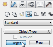
The position of the camera and the target don't matter, as you will change these later.
The walkthrough shows part of the den of the house, not the entire house, which would take considerable time to generate.
Zoom in to the area you will edit:
 (Zoom Extents).
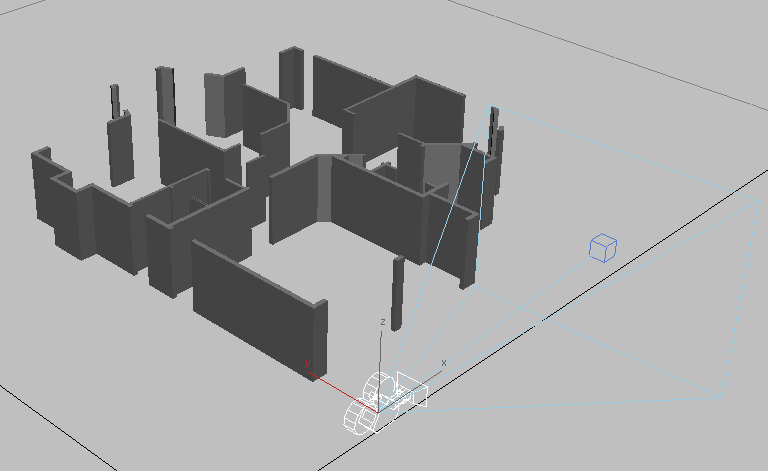
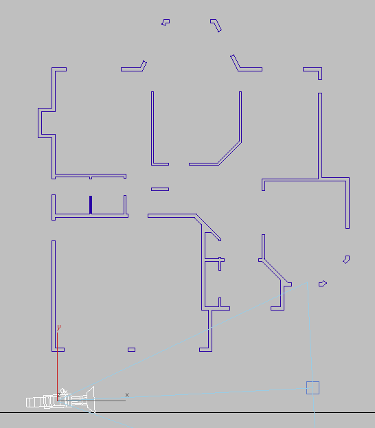
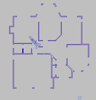
Now you should see the floor plan and the camera.
Press F3 to switch to Wireframe display mode, if necessary, and if the Top viewport shows a grid, press G to turn off grid display.
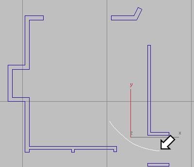
 (Zoom Region), and in the viewport, drag a rectangle to zoom in closer on the area where the hall approaches the den (the
den is the room at the upper left of the house).
(Zoom Region), and in the viewport, drag a rectangle to zoom in closer on the area where the hall approaches the den (the
den is the room at the upper left of the house). Create panel. Turn on
  (Shapes). On the Object Type rollout, click the Line button to turn it on.
Once you have created the curve, you can edit it by selecting it, going to the Modify panel, and then clicking Vertex to go to the Vertex sub-object level. Move individual vertices until the line appears the way you want it, and then turn off Vertex.
If you deselected the line,  select it again, go to the
  Modify panel, and then use the name field at the top of the panel to rename the line.
The path was created at a height of zero. If you moved the camera along it, the camera would be moving at ground level! You need to move the path upward.
(Zoom Extents).
 Drag the path upward along the Y axis until it's a little over five feet high (watch the Y coordinate display on the status
bar while you're dragging the path).
Drag the path upward along the Y axis until it's a little over five feet high (watch the Y coordinate display on the status
bar while you're dragging the path).
Attach the camera to the path:
(Zoom Extents).
Click the camera object to select it.
 Constraints Path Constraint.
A rubber band line appears, leading from the camera to the cursor location.
3ds Max Design repositions the camera so it is located on the path.
 (Play Animation) to view the animation generated by the Path constraint.
The camera moves along the path. However, the target, which is stationary, is not in the proper location. You will fix this in the following procedure.
 (Stop Animation) to stop playback.
As you move the target, the camera rotates to remain aimed in the target's direction.
(Zoom Extents).
The target is still at ground level (Y=0), so the camera is aimed at the floor.
Move the target upward along its Y axis until it is about the same height as the path.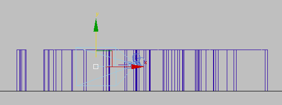
Now both the camera and its target (point of view) are at approximately human height.
CameraDen (or press C).
This view corresponds to what the camera sees. If the view isn’t already shaded, press F3 to display the view in shaded mode.
(Play Animation) to preview the walkthrough.
(Stop) to stop playback.
Set the camera's field of view:
The room is fairly small. Decreasing the camera's focal length and increasing its field of view (FOV) lets the camera show more of the room.
 Save As, and save the file as my_wt_camera.max.
If you want to do additional editing of the camera position, move the path to which it is attached, or the vertices of that path. You can't move the camera itself, because it is constrained to this path. You can move the camera’s target, if you want to.