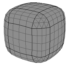
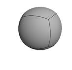
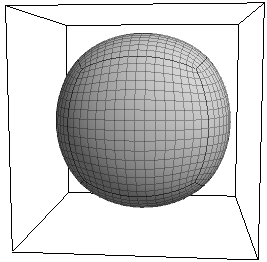
Subdivision surfaces (sometimes called " subdees") are a method of creating a high-resolution polygonal mesh from a low-resolution one. You can use the low-resolution mesh as a hull to control the high-resolution mesh.
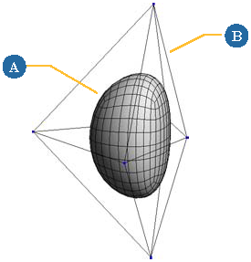
A subdivision surface (A) with its polymesh hull (B).
Subdivision surfaces have numerous advantages. They provide the smoothness of NURBS surfaces with the local detail and texturing capabilities of polygonal meshes.
You can work with the simpler and lighter hull rather than the heavy, denser, high-resolution version for faster interaction.
You can transform, deform, envelope, and shape-animate the control hull and the effect propagates automatically to the subdivision surface.
You can even add and remove points, edges, and polygons from the hull to update the surface.
There are three ways to subdivide polygon meshes: generating a new object, modifying the geometry approximation, and locally subdividing selected polygons. You can also combine these methods to obtain the results you want.
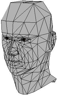
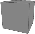
You can create a new high-resolution polygon mesh object from a low-resolution one. As long as there is a modeling relation between the two objects, you can modify and animate the low-resolution object to drive the high-resolution one.

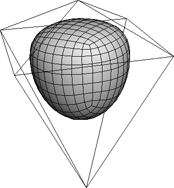
Generated subdivision surface: The low-res object (A) drives the overall shape of the high-res subdee (B). You can still move points on the subdee independently (C).
You can hide the high-resolution object while you animate and modify the low-resolution version. You can also turn off the Render Visibility of the low-resolution model.
Alternatively, you could place the low-resolution object in a non-rendering layer and the high-resolution version in a non-viewable layer while you work.
In addition, you can apply a Display property so that the low-resolution version is always displayed in wireframe. These procedures are described in detail in Choosing How to Display Specific Objects.
The advantages of this method is that you can move points and add detail to the generated object yet still drive it with its control hull. You can also create multiple high-resolution objects from the same low-resolution one.
A disadvantage is that the high-resolution object's geometry can result in heavy scenes and large files.
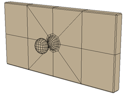
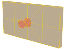
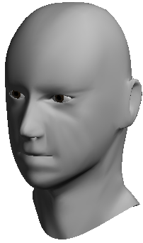
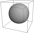
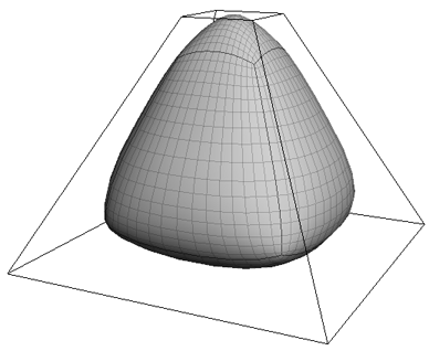
You can turn a polygon mesh object into a subdivision surface by applying a geometry approximation property. This method does not create a new object; instead, it creates an alternative geometry that is used for rendering.
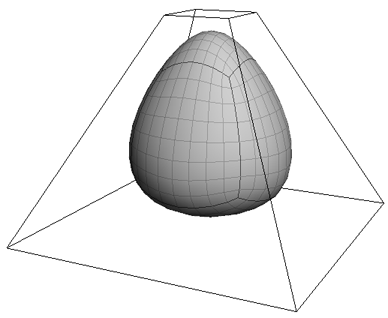
Geometry approximation: The low-res hull and the high-res subdee are part of the same object.
The original mesh becomes the control cage of the new geometry. The advantage of this method is that no new geometry is actually created, so scene files can still be quite small.
The main disadvantage is that you cannot manipulate individual points, etc., on the high-resolution geometry; only the components that correspond to components on the control cage. However, you can create a duplicate based on geometry approximation that preserves materials, textures, and vertex colors — see Duplicating Using Geometry Approximation.
You can add subdivisions locally to selected polygons of a mesh. This method adds an operator to the polygon mesh's operator stack and modifies its topology.
It is useful for adding detail exactly where you want it. Although new geometry is created, you control the amount and the location.
You can combine the methods of subdivision to achieve the control and effect you want. For example, you can start with a very rough polygon mesh as an animation cage. Because it has few points, it is very easy to envelope and manipulate.
From this basic mesh, you can generate a new subdivision surface as a texturing cage. Because it is a new object rather than an alternative representation of the same geometry, you can move points and add local subdivisions where needed. It has more points than the animation cage, so you have more control over texture positioning, but not so many more points to make texturing too difficult.
Finally, you can apply a geometry approximation property to this intermediate object so that you can render a very smooth, seamless object.
Many different algorithms have been devised for subdividing polygons and averaging vertex positions. Softimage gives you a choice of several of these algorithms: Catmull-Clark, XSI-Doo-Sabin, and linear. In addition, you have the option of using Loop for triangles when using Catmull-Clark or linear. The determining factor between choosing one method over another depends on your personal preference and what you are trying to accomplish, although not all rules are available with all operations.
The Catmull-Clark subdivision algorithm produces rounder shapes. The generated polygons are all quadrilateral. The higher the subdivision level, the more this method approximates a bi-cubic standard B-spline surface. The geometry produced is compatible with the method described in "Recursively generated B-spline surfaces on arbitrary topological surfaces" by E. Catmull and J. Clark (Computer-Aided Design 10(6):350-355, November 1978).
In areas where the original mesh has quads, the surface has C2 (curvature) continuity; in areas where there are non-quad polygons or vertices without exactly four edges, the surface has C1 (tangential or parametric) continuity.
At level 1, each n-sided polygon yields n quads; at each additional level every quad yields four more quads.
The XSI-Doo-Sabin subdivision algorithm is a variation of the standard Doo-Sabin algorithm. It produces more geometry than Doo-Sabin, but it works better with cluster properties such as texture UVs, vertex colors, and weight maps, as well as with creases.
The higher the subdivision level, the more this method approximates a bi-quadratic uniform B-spline surface.
In areas where the original mesh has quads, the surface has C1 (tangential or parametric) continuity; in areas where there are non-quad polygons or vertices without exactly four edges, the surface has G1 continuity (that is, the tangents have the same direction but not necessarily the same length).
Linear subdivision does not perform any smoothing, so the object's shape is unchanged. It is useful when you want an object to deform smoothly without rounding its contours.
With the Catmull-Clark and linear subdivision methods, you have the option of using Loop subdivision for triangles. The Loop method subdivides triangles into smaller triangles instead of into quads, which gives better results when smoothing and shading.
The Loop method avoids the bulging and pinching that can occur with triangles when using strictly quad-based methods such as Catmull-Clark. Catmull-Clark or linear is still used for non-triangles, and there is a smooth transitions between Loop and Catmull-Clark at boundaries between triangles and non-triangles.
There is an option in the Modeling preferences to activate Loop for triangles by default.
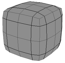
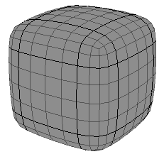
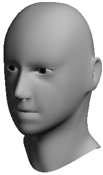
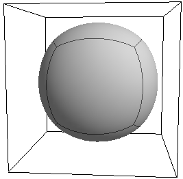
With any subdivision method, you can specify the number of levels. This controls how many times the subdivision process is iterated. Higher levels provide for greater detail and smoothness, but result in heavier geometries and longer processing.
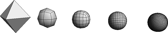
Different levels of subdivision
The subdivision level is animatable, so for example, you can set an expression to control it based on the distance from the camera.
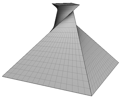
Subdivision surfaces typically produce a smooth result because the original vertex positions are averaged during the subdivision process. However, you can still create sharp spikes and creases in subdivision surfaces.
This is done by adjusting the hardness value of points or edges. The harder a component, the more strongly it "pulls" on the resulting subdivision surface. Values higher than the subdivision level have no further effect. For details, see Making Creases and Spikes.
There are several visibility options you can set when working with subdivision surfaces. These affect only subdivision surfaces created using the geometry approximation method.
You can display the low-resolution hull and the high-resolution surface independently.
Polymesh Hulls controls the display of the low-resolution hull. Turn this option off to simplify the view, for example, if the hulls make it difficult to see the final subdivision surface.
Subdivision Surfaces controls the display of the final, high-resolution surface itself. Turn this option off to speed up interaction when you do not need to see the end result.
Boundaries and hard edges are shown directly on the surface if the hull is not displayed and Boundaries and Hard Edges are visible in the 3D view.
If both options are on, then the hull is always shown in wireframe, even in constant, shaded, and textured display modes.
To affect the display of selected objects in a single 3D view, click the eye icon (Show menu) and toggle Polymesh Hulls and/or Subdivision Surfaces.

To affect the display of selected objects in all open 3D views, toggle Polymesh Hulls and/or Subdivision Surfaces from the Display  Attributes menu on the main menu.
To affect the display of both selected and unselected objects in a single 3D view, open the Camera Visibility property editor by pressing Shift+S or choosing Visibility Options from the eye icon (Show menu), and then set the Polymesh Hull and Subdivision Surface options on the Attributes tab.
The left checkboxes affect the display selected objects and the right checkboxes affect the display of unselected objects.
To affect the display of both selected and unselected objects in all open 3D views, open the Camera Visibility property editor
by choosing Display Visibility Options (All Cameras) from the main menu and then set the Polymesh Hull and Subdivision Surface options on the Attributes tab.
The left checkboxes affect the display selected objects and the right checkboxes affect the display of unselected objects.
To quickly toggle the display of polymesh hulls in all open 3D views, press Ctrl+plus (+ key on the numeric keypad).
You can choose to display a simplified or a detailed version of the subdivision wireframe. For example, you may prefer to see the detailed version while you are modeling and the simplified version while you are animating.
For subdivision surfaces created with the geometry approximation method, you can select and move components directly on the subdivision surface, when both subdivision surfaces are visible and polymesh hulls are not visible.
You can select those edges that correspond to edges on the hull. Those edges are indicated by thicker lines.
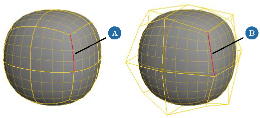
This selected edge on the subdivision surface (A) corresponds to this edge on the polymesh hull (B).
You can select the "patches" that correspond to polygons on the hull. These are the areas bounded by thicker lines.
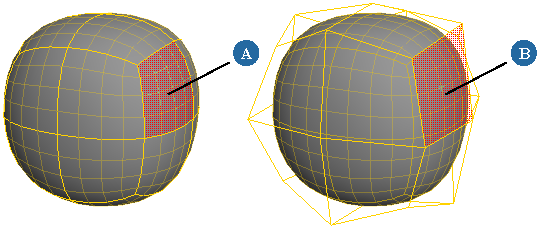
This selected patch on the subdivision surface (A) corresponds to this polygon on the polymesh hull (B).
You can select points that correspond to points on the hull. These are the points at the intersections of the thicker lines.
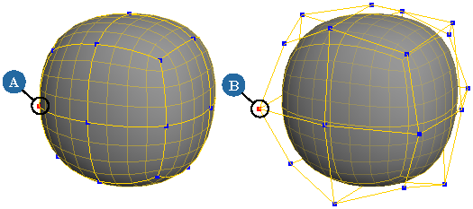
This selected point on the subdivision surface (A) corresponds to this point on the polymesh hull (B).
Once a component on the subdivision surface is selected, you can perform almost any modeling operation: transform, deform, delete, subdivide, split, bevel, extrude, and so on. This means that you can effectively model without displaying the hull.
 Except where otherwise noted, this work is licensed under a Creative Commons Attribution-NonCommercial-ShareAlike 3.0 Unported License