Extrudes selected polygons, edges, or points of a polygon mesh along their normals.
To apply: See Copying Components Along Their Normals [Modeling].
To redisplay: Select the polygon mesh object then choose Selection and click the Extrude Normal Op icon.
| Length |
Distance to extrude in SOFTIMAGE units. If you are defining shapes in local shape mode, it is better to adjust this parameter than to translate the components interactively. Otherwise, you might not get the expected results as the local reference frame changes. |
| Subdivs |
Number of subdivisions along the axis of extrusion. |
| Inset Amount |
Shrinks the boundary of the new polygons by the specified amount in Softimage units. 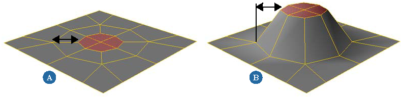 Negative values expand the boundary instead of shrinking it. If the extrusion length is 0, the resulting polygons will overlap. If you do not want overlapping polygons, you should offset the polygons (see Offsetting Polygon Contours) before insetting them. 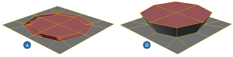 This option applies only to polygons, not to edges or points. |
| Inset Locked |
Controls how the amount of insetting is specified. This option is not available when Length is 0.
This option applies only to polygons, not to edges or points. |
| Angle |
The amount of insetting specified as an angular difference from the normal in degrees. This option is available only when Inset Locked is on, and it applies only to polygons, not to edges or points. 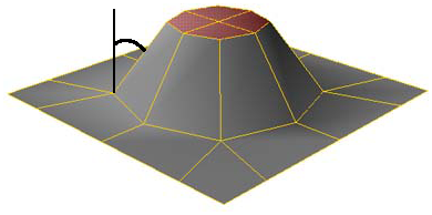 |
| Extrude Along Vertex Normals |
Uses the vertex normals instead of the polygon normals. This can give better results, particularly on curved surfaces. |
| Duplicate Polygons |
Controls how polygons are copied.
This option applies only to polygons, not to edges or points. |
| Maintain Orthogonality |
Ensures that the Y axis of the reference frame is orthogonal to the selected components even when the object has been scaled non-uniformly. Only the existing transformations when the extrusion is applied are considered; if the object is animated or transformed later, the new values are not considered. |
| Skirting Ratio |
When extruding edges and points, controls the width at the base. Lower values produce sharper spikes and creases. 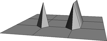 With multiple Subdivs, this parameter controls the curvature of the extrusion profile. 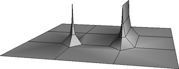 |
 Except where otherwise noted, this work is licensed under a Creative Commons Attribution-NonCommercial-ShareAlike 3.0 Unported License


