Subprojections allow you to reproject a texture onto selected polygons of an already-textured object in a way that better conforms to that selection's shape. For example, you could cylindrically reproject a texture on the cylindrical band at a sphere's equator. This simplifies the texturing process by allowing you to project a texture onto an object in several different ways, while only having single set of UV coordinates to manage.
While the subprojections behave like any other group of points in the texture editor, they have their own manipulators in the 3D views so you can transform them independently of their parent projections.
You cannot, however, adjust a subprojection on the surface of the object using the texture projection manipulator (which you activate by pressing J).
To apply a planar, cylindrical, spherical, or cubic subprojection
Select any number of points or polygons on your object or model. You can select them from the texture editor work area or from any 3D view.
Click the planar  , cylindrical
  , spherical
  , or cubic subprojection
 button on the Texture editor command bar, or select a subprojection from the Tools menu to open the subprojection menu.
From the subprojection menu, click one or more of the following options to activate or deactivate them:
Position Relative to Object positions the subprojection's manipulator relative to the entire textured object rather than the selected points or polygons.
If you select a Best Fit projection, the Position Relative to Object setting is ignored.
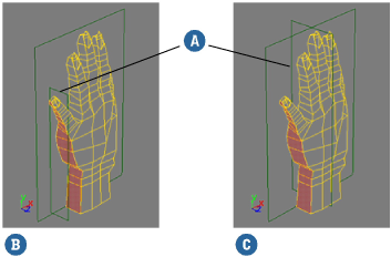
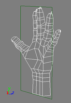
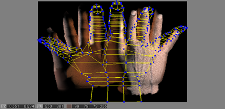
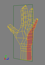
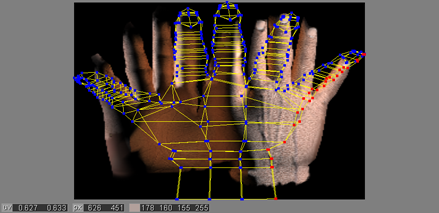
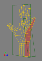
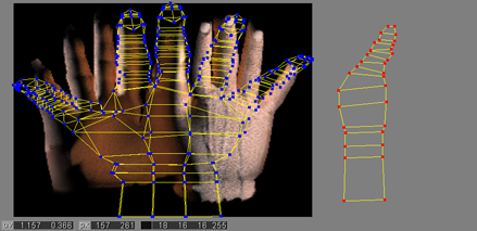
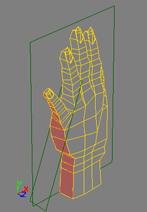
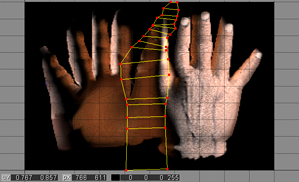
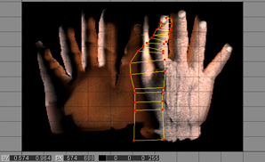
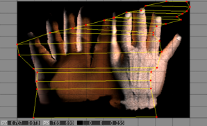
Both hands have a YZ planar subprojection applied to the selected polygons. The subprojection manipulator is marked (A).
When the Position Relative to Object option is inactive, the subprojection's manipulator is positioned relative to the selected polygons (B).
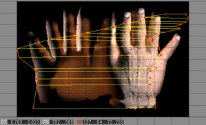
When the Position Relative to Object option is active, the subprojection's manipulator is positioned relative to the entire object (C).
Maintain Aspect Ratio matches the subprojection's aspect ratio in the texture editor to that of the selected points or polygons on the object as closely as possible.
If the Fit to Image option is active, the subprojection is scaled to the largest size possible without distorting the aspect ratio. See the following illustration of how aspect ratio and fitting work together.
Fit to Image fits the subprojection to the entire texture image in the texture editor.
If the Maintain Aspect Ratio option is active, the subprojection is scaled to the largest size possible without distorting the aspect ratio. See below for an illustration of how aspect ratio and fitting work together.
Choose a plane of projection (Best Fit, XY Object Aligned, YZ World Aligned, and so on) from the menu to complete the subprojection operation. The last plane of projection used appears in the menu in bold type. The subprojection is applied to the object and its manipulator appears in the 3D view.
Transforming Subprojections in the Texture Editor
Since subprojections are groups of points that have been reprojected, you can scale, rotate, or translate them as you would any other group of points in the texture editor.
Transforming Subprojections in a 3D view
In the 3D views, subprojections are graphically represented by their own texture support objects. You can scale, rotate, or translate them as you would any other texture support object. When you transform the subprojection in a 3D view, the corresponding points are moved accordingly in the Texture Editor.
Editing Subprojection Support Properties
You can also the properties of subprojection supports as you would any other texture support object. This is especially convenient for cubic subprojections because it allows you to apply cubic projection presets, set a face projection method, and transform the faces of the cube individually.
Contour Stretch type Subprojections
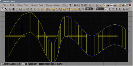
Like planar, cylindrical, and spherical subprojections, contour stretch subprojections allow you to reproject a texture image onto a selection of an object's polygons. Rather than reprojecting according to a specific form, however, a contour stretch subprojection analyzes a four-cornered selection to determine how best to stretch the polygons' UV coordinates over the image.
Contour stretch subprojections do not have the same alignment and positioning options as other subprojections. Instead, you select a stretching method that is appropriate to the selection's topology and complexity. Also, contour stretch subprojections do not have a manipulator in 3D views. You can adjust them only from the texture editor.
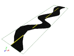
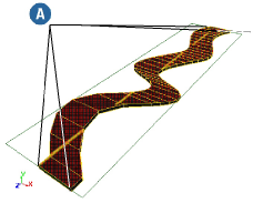
Contour stretch subprojections are useful for a number of different texturing tasks, particularly for applying textures to tracks, and irregular, terrain-like meshes. They are also useful for fitting regular-shaped textures onto curved meshes. For example, they would be useful to place a label texture on a beer bottle, right at the junction of the bottle's neck and body.
Although the easiest selection for a contour stretch is a perfect quad, it's more likely that you'll want to use contour stretch subprojections on less regular shapes. This is not a problem so long as you keep a few simple guidelines in mind when you make your selection.
The selection cannot be a whole object, it must be a selection of polygons with an identifiable contour.
Although the selection doesn't have to be perfectly rectangular, the contour stretch projection must be able to derive four corners from its contour.
If the selection has holes in it, it is more likely to produce undesirable results.
If the selection consists of two or more discontiguous "islands," their UV coordinates do not remain separated in the texture editor once the projection is applied. Instead, they are treated as a single "one-piece" selection.
To apply a contour stretch subprojection to a selection of components
Select any number of points or polygons on your object or model. You can select them from the texture Editor work area or from any 3D view.
Remember that the selection must have four discernible corners (even if it isn't perfectly rectangular) and a clear contour.
Click the contour stretch subprojection button on the Texture editor command bar, or choose Contour Stretch Subprojection from the Tools menu to open the subprojection menu.
From the subprojection menu, activate or deactivate the Maintain Aspect Ratio option as needed.
Activating this option matches the subprojection's aspect ratio in the texture editor to that of the selected points or polygons on the object as closely as possible.
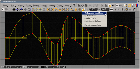
Choose a stretching method to complete the subprojection operation (the last method used appears in bold type in the menu). The following methods are available:
Walk ing on the Mesh from Contours calculates the UV coordinates by following the mesh as closely as possible from contour to contour, in both the U and V directions, and accumulating edge distances from the selection's borders. This option usually gives the best results, particularly on complex meshes.
Spatial Distance from Contours calculates the UV coordinates by travelling from border to border without trying to follow the mesh. This method works well on meshes that are relatively flat, and whose contours are more or less parallel. It also tends to be faster to calculate than other methods, especially on simple meshes.
Walking NxM Regular Quads from Contours calculates the UV coordinates by walking from border to border and trying to build parallel border lines to produce a grid-like structure. This is most effective for uniform-density meshes of NxM rectangular quads. It may produce undesirable results when the mesh is irregularly shaped.
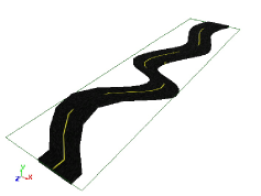
Projection on Surface Built from Contours creates an internal parametric surface using the contours and borders of the polygon selection and then projects the polygon selection onto that surface to calculate its texture coordinates. This method is especially useful for bumpy, terrain-like surfaces.
Once you select a method, the object's points are displayed in 3D views and a pick session begins. Do one of the following:
The subprojection is applied and the PolyUVContourStretching property editor opens.
Adjust the options in the property editor as needed. This is often useful if you weren't sure which stretching method to use. See Poly UV Contour Stretching Property Editor.
You can now continue to adjust the subprojection's position and dimensions in the texture editor as you would any other group of sample points.