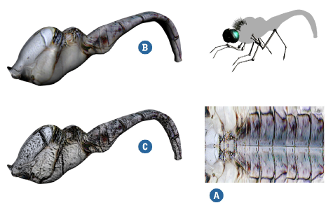
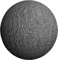
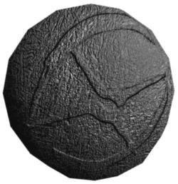
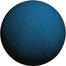
Although real surfaces can be perfectly smooth, you are more likely to encounter surfaces with flaws such as indentations and ridges. One of the most basic ways to create these types of "bumps" on a surface is to use a bump map.
A bump map simulates relief on objects by perturbing the shading normals according to a texture. The result is the illusion of bumps, ridges, and imperfections. However, there is no change to the objects' geometry, so there is no change to an object's silhouette or the shadow it casts.
When you create or select an image to use as a bump map, remember that grayscale or black-and-white images are easier to work with. That's because you can quickly identify how the bump map will appear on the target surface.
Depending on how you create the bump, light areas can appear raised or lowered.
Using the Bumpmap node, light areas are raised and dark areas are lowered.
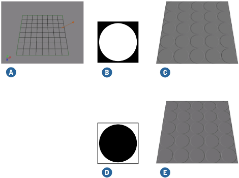
Using the Bumpmap Generator node or using the bump controls in a texture shader, light areas are lowered and dark areas are raised.
Either way, you can invert the effect by setting a negative value for Bump Scale in the Bumpmap node, or a negative value for Factor in the Bumpmap Generator or texture shader.
Creating a Bump Map in the Render Tree
You can apply a bump map to an object's surface independently of a texture or color by using the Bumpmap shader in the render tree. This allows you to control an object's bump-mapping independently of its color.
To create a bump map in the render tree
Open a render tree (press 7) and click Update in its command bar.
Choose Nodes  Bump Bumpmap from the menu to add a Bumpmap shader to the render tree work area.
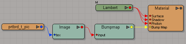
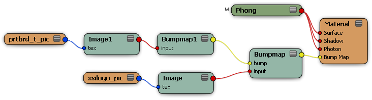
Connect the Bumpmap shader to the material node's Bump Map input, and connect an image or shader tree to the Bumpmap's input. The render tree might look something like this:
|
|
Determine the strength of the bumping by adjusting the Bump Scale parameter. The larger the factor, the "bumpier" the texture appears. A positive value bumps outward and a negative value bumps inward.
If necessary, adjust the Sample Spacing. Larger values result in a blurrier map, while smaller values give a sharper result.
To create a more refined or detailed bump map, you may want to combine two or more bump maps onto the same object. This can be done as easily as adding a second bump map.
To combine multiple bump maps, connect another Bumpmap node to the Bumpmap's bump input. The first node will perturb the normal before calling the second node. This allows you to create more detailed or refined bumps, for example, using one map for coarse detail and another one for fine noise.
|
|
Other Ways of Applying Bump Maps
As an alternative to using the Bumpmap shader, there are other ways of applying bump maps:
You can use the Bumpmap Generator if you want to use one of its projection options.
You can use the Image shader's built-in bump controls. This can be useful, for example, if the texture image's alpha channel contains the bump information.
Using a Separate Projection for Bump Mapping
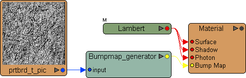
You can use a Bumpmap Generator instead of a Bumpmap node if you have special projection requirements. You can plug an image clip directly into a Bumpmap Generator because it has its own projection options.
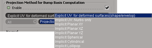
When you apply a bump map to an object, discontinuities in the object's UV coordinates can cause artifacts in the rendered object. The Bump Map Generator shader contains options that allow you to specify a second projection, with its own set of UV coordinates, used only for the bump map computation. You can find these options in the Projection Method for Bump Basis Computation options of the Bump Map Generator shader's property editor.
The following parameters control the bump-basis computation's UV coordinates:
Enable activates the projection for the bump basis computation.
The first Texture Projection list specifies the type of projection to use. Choose one of the following:
Explicit UV: for deformed surfaces (shape/envelope) uses an explicit texture projection. Choosing this option activates the second Texture Projection list from which you can choose an explicit projection type.
Implicit UV (Nurbs only) uses an implicit UV type projection to compute the bump map. Because the projection is implicit, the UV coordinates are calculated at render time and not added to the object as they would be with an explicit projection. This projection type only works for NURBS objects.
Implicit Planar (XY/XZ/YZ)/ Spherical/ Cylindrical/ Lollipop uses an implicit projection of the specified type to compute the bump map. Because the projection is implicit, the UV coordinates are calculated at render time and not added to the object as they would be with an explicit projection.
You can also negate the color values of the texture that is driving the bump map by using the Mix 8 Colors shader. This is useful if you wish to use several textures to create the bump map.
Creating a Bump Map Using the Texture Image Shader
You can apply a texture and use the texture's built-in bump mapping options. This is a fast way of applying a bump map, but offers less control than other ways. It can be useful, for example, if the texture's alpha channel contains the bump information.
Select one or more objects to which you want to apply a bump map.
Apply a texture shader to the object, group, or hierarchy by choosing Get Texture. The selected texture's property editor appears.
If you chose the Image file, select an image clip to use as a bump map. You can choose from available image clips or create a new one by clicking New.
Define a texture projection for the texture (by clicking New) or use an existing texture projection from the Texture Projection menu.
If you have a render region open, you will notice that the texture has been applied to your object.
To activate the bump map, select Enable in the Bump Mapping options of the texture shader's property editor.
If you want to use the image's alpha channel to control the bump map, activate the Copy Alpha to RGB option so that the texture shader calculates the alpha channel instead of the RGB values.
Determine the strength of the bumping by adjusting the Bump Map Factor.
The higher the factor, the "bumpier" the texture appears. A positive value bumps outward and a negative value bumps inward.
If necessary, adjust the Step values. This defines the UV offset within which the shader evaluates the object surface to determine the surface orientation.
The larger the texture used, the smaller the Step value should be. Typically, the Step value should be set in the 0.001 to 0.05 range. Larger values produce low quality bump maps with large numbers of artifacts.
Bump Mapping Using Normal Maps
Normal maps are images that store an object's normals as color values such that the Red, Green and Blue channels correspond to the X,Y and Z directions. Each pixel in the normal map image indicates the direction that the corresponding point on the object surface is facing. You can use this information to create highly detailed bump maps.
The Normal Map shader allows you to use a normal map as a bump map.
You can create normal maps for objects using the RenderMap property, as described in Generating the Normal Maps, or using the Ultimapper tool, as described in Transferring Surface Attributes (Ultimapper).
To create a bump map from a normal map
Open a render tree (press 7) and click Update in its command bar.
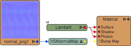
Choose Nodes Bump Normal Map from the menu to add an XSI Normal Map shader to the render tree work area.
Connect the XSI Normal Map shader to the material node's Bump Map input.
Double-click the XSI Normal Map to open its property editor.
From the Map options, choose a normal map image for the bump map.
From the tspaceid options, choose a texture projection for the normal map image, or click New to create a new one.
From the Tangents options, choose the Color at Vertices (CAV) property where the object's tangents are stored, or click New to create a new one. Tangents are required for the bump map computations.
Bump mapping renders badly when the texture repeats
When you use a repeating texture to control a bump map, the bump Step value should be divided by the number of repeats in order for the sampling achieve the necessary precision.
You can solve this problem by using scripting to divide the current Bump Mapping Step value by the number of repeats in each axis.
Bump mapping renders badly on scaled objects
Bump mapping is scale-dependent. When you scale a bump-mapped object and then render it, you'll begin to notice artifacts that become more severe as the scaling becomes more extreme.
This is because scaling increases the object's size relative to its parent's center, but does not deform its points, whose distance from the object's center stays the same. Think of scaling as magnifying the object without changing its geometry.
As a result, each step in the bump map covers the same percentage of a larger object, resulting in a coarser bump map.
There are two solutions to this problem:
You can use scripting to divide the Bump Mapping Step value by the scaling factor for each scaled axis.
This adjusts the bump map such that each step covers less of the larger object, resulting in a finer bump map with fewer artifacts.
You can freeze the object's scaling. This resets its XYZ scaling values to 1,1,1 relative to its parent's center. The objects points are deformed to compensate, and the object's size appears not to change.
In this case, you don't need to adjust the Bump Mapping Step value because each step covers a smaller percentage of the now larger object, resulting in a finer bump map with fewer artifacts.


