You can modify surfaces in a variety of ways using the commands in the Modify  Surface menu of the Model toolbar. You can:
You can add knot curves to increase the resolution of a surface. You can also add multiple knot curves at the same position (multiknots) to create sharp ridges.
Select a U or V isoline or a U or V knot curve on a surface.
Choose Modify Surface Insert Knot.
The knot curve is added and the Insert Surface Knot property editor opens.
Use the Knot Multiplicity slider to specify the continuity of the knot. For more information, see Multiplicity.
Use the options in the Surface Curve Adaptor page to fine-tune the position of the new knot curve.
If you add a knot curve to a subsurface of an assembled surface mesh, it is automatically propagated across any junctions to maintain the alignment of control points on subsurfaces.
For more information about surface meshes in general, see Surface Meshes.
You can remove knot curves to decrease the resolution of surfaces. For multiknot curves, you can choose how many knot curves to remove.
Press Delete or choose Modify Surface Remove Knot.
If you did not select a curve in step 1, you can pick a surface and knot curve now. The knot curve is removed and the Remove Surface Knot property editor opens.
The Knot Multiplicity parameter lets you remove some or all of the knot's multiplicity (in the case of multiknots).
The parameters on the Surface Curve Adaptor page let you change which knot curve to remove.
You cannot remove a knot curve if it is a boundary. You can use Snip to achieve the desired effect — see Snipping Surfaces.
If you remove a knot curve on a subsurface of an assembled surface mesh, it is automatically propagated across any junctions to maintain the alignment of control points on subsurfaces.
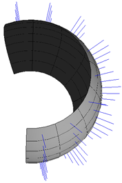
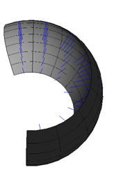
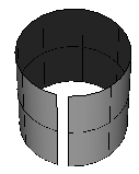
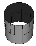
You can open a closed surface and close an open surface. A surface can be open in both U and V like a grid, closed in both like a torus, or open in one and closed in the other like a tube.
Choose Modify Surface Open/Close from the Model toolbar.
If you didn't pick anything in step 1, you can pick a surface now. The Open/Close Surface property editor opens.
Specify the directions in which to open or close the surface.
Closed surfaces always open up at their U = 0 or V = 0 boundary — you can shift the boundary position of a closed surface as described in Shifting UV on Surfaces.
To open a surface along an arbitrary isoline, first add a knot curve at that position then shift the boundary to the new knot curve.
If a surface is closed in a direction, you can shift the boundary (U = 0 or V = 0 position) along the surface.
Select a U or V knot curve or a U or V isoline on a surface.
Choose Modify Surface Shift UV.
If you didn't select anything in step 1, you can pick a surface and knot curve now.
The corresponding U or V boundary is shifted to the selected knot curve (or in the case of an isoline, to the knot curve before the isoline according to the surface's parameterization) and the Surface Shift property editor opens.
If necessary, adjust the parameters. As you change values, the corresponding boundary jumps to the knot curve before the parameter value.
You can swap the U and V directions on a surface. This simply changes which direction is considered U and which is V for the purpose of other modeling and texturing operations; it does not change the object's shape. The new U direction is the old –V and the new V is the old U, preserving the direction of the normals.
Cleaning a surface reduces the number of control points while keeping the same general shape.
Choose Modify Surface Clean from the Model toolbar.
If you didn't select anything in step 1, you can pick a surface now. The surface is resampled and Clean Surface property editor opens.
Specify the directions in which to clean. You can also set Tolerance separately for U and V; the tolerance controls the maximum difference between the original curve and the resampled shape.
Parameterization refers to the way that any position on a surface is described in terms of the parameters U and V. Different parameterizations give different behaviors as you manipulate the surface.
When you reparameterize a surface, the new parameterization is in effect at the position of the Reparameterize operator in the operator stack. If you move points or perform other operations on the surface after reparameterizing, the resulting parameterization might not be the same.
When you create a UV texture projection, it is based on the parameterization at the moment of creation. For example, if you want a chord length parameterization for your projection, make sure to reparameterize the surface right before you create the projection. If you reparameterize after applying a UV projection, the texture may shift because the texture returns the color information for a particular UV position but the reparameterization moves that UV position to another location on the surface.
For a description of the available parameterization methods, see Parameterization.
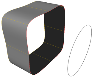
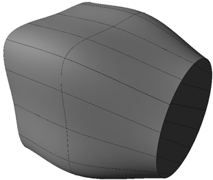
You can extend a surface object to a curve.
|
|
The original surface and curve, and the modified surface.
Select a boundary on the surface, then add a curve to the selection. You can select curve objects as well as isolines, knot curves, boundaries, surface curves, and trim curves.
Choose Modify Surface Extend to Curve on the Model toolbar.
If you didn't pick both a boundary and a curve in step 1, you can pick the missing inputs in order now. The surface is extended and the Extend to Curve property editor opens.
Adjust the parameters as desired. For more information, see Extend to Curve Property Editor [Properties Reference].
You can stitch the boundaries of two surfaces together. This is similar to merging (described on Reparameterizing Surfaces.
Select two surface boundaries then (optionally) add an intermediary curve to the selection.
Choose Modify Surface Stitch from the Model toolbar.
If you did not select two surface boundaries and an intermediary curve, you can pick the missing inputs in order now.
Right-click to terminate the picking session without choosing an intermediary curve.
The surfaces are stitched and the Stitch Surfaces property editor opens.
Set options as desired. For more information, see Stitch Surfaces Property Editor.
Use the Tolerance option on the Clean page to specify the maximum error for calculating the merged surface. Lower values result in more subdivisions.
Use the options on the Shape page to adjust the overall shape of the blend. In particular, if you selected a curve to pass through, set Seam to Curve.
You can snip a surface along an arbitrary isoline, keeping one portion and discarding the other.