The quickest and easiest way of animating an object along a path is by using the Set Path command and picking the curve to be used as the path. When you use this command, the animation is created for you. There's no need to set keyframes — just set the start and end frames.
A percentage (perc) function curve is created with your choice of spline (ease-in/ease-out) or linear interpolation. After you have created path animation, you can modify the timing by editing this function curve (see Modifying the Path Timing) or you can change the path curve itself to change the animation (see Modifying the Path Curve or Trajectory).
To animate an object along a path
Create a curve using any of the available tools in the Curve menu on the Model or Animate toolbars.
Select the object you want to animate.
In the dialog box that opens, enter the frame at which the object starts moving (Start Frame) and the frame at which the object reaches the end of the path (End Frame). By default, the object travels the full length of the path.
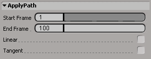
If you want the object to move along the path at a constant speed, select Linear. Otherwise, the object will ease into and out of the animation.
If you want the object's X axis (by default) to stay aligned with the path's slope, select Tangent. The constrained object's axis is repositioned to point in the direction of the curve's slope. As the object moves along the path, its X axis follows the curve's slope.
For more information on tangency constraints, see Tangency Constraints.
Click OK and pick the curve to use as the path. Keys are created at each end of the path, and the object's intermediate position along the path is interpolated.
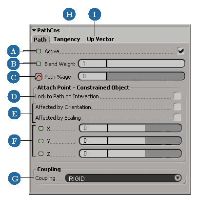
After you pick the path curve, the PathCns property editor opens, allowing you to manually adjust the settings.
The Path %age (percentage) slider is especially important for controlling how much of the curve is used as a constraining force on the selected object.
| A |
Toggles the activeness of the path constraint. See Activating and Deactivating Constraints for more information. |
| B |
Blends the weight of this constraint with other constraints on the constrained object. See Blending Constraints for more information. |
| C |
The percentage of the curve that is used as the constraining force on the constrained object. |
| D |
Prevents object from being moved off the path when interactively translating it (unless CnsComp is on). |
| E |
The constrained object is affected by the rotation and/or scaling of the path. |
| F |
Sets an offset distance on the XYZ axes between the constrained object and the path. See Creating Offsets between Constrained and Constraining Objects for more information. |
| G |
How closely constrained object follows path (soft or rigid) if there is an offset. See Setting the Coupling Behavior between Objects for more information. |
| H |
Keeps the constrained object tangent to the path. If you selected the Tangent option in the Apply Path dialog box, the Active option is selected on the Tangency page here. See Tangency Constraints for more information. |
| I |
Constrains the up vector direction of the object. See Up-vector Constraints for more information. |
To modify the path timing, see Modifying the Path Timing; to modify the path curve itself, see Modifying the Path Curve or Trajectory.
To remove the animation, see Removing Path or Trajectory Animation.
This example shows you how to apply path animation to the camera and its interest.
Create a cityscape using cubes and a grid
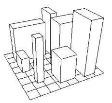
Choose Get  Primitive Polygon Mesh Grid and Get Primitive Polygon Mesh Cube to create objects for a cityscape.
Using Edit Duplicate Multiple, create several copies of the cube. Scale them so that they are all different sizes and place them on the grid, using the
illustration above as a reference.
Choose Create Curve Sketch from the Model or Animate toolbar and draw a free form curve path that goes through the city.
To select the camera, do one of the following:
Choose Create Path Set Path from the Animate toolbar. Use the default values for the start and end frames, select Linear, and click OK,
Play back the animation. You will notice that the camera is following the path but the camera interest stays fixed.
Select the camera interest by clicking it in a viewport or the explorer.
Choose Create Path Set Path, and set the start and end frame values to –20 and 280. Pick the curve path.
Play back the animation. The camera interest is now traveling along the path slightly ahead of the camera.


 in the viewport title bar and choose