The PointPosition attribute is a 3D vector that is available to get and set on any geometric object.
When you get an object's PointPosition values, they are expressed in terms of that object's local reference frame, not in terms of the object on which the ICE tree exists (the "self" object). The same is true of PointVelocity, PointNormal, and similar attributes.
On the other hand, if you get data such as PointPosition from a location, it is expressed in terms of the "self" object's local reference frame. This makes it easy, for example, to set points' Force or PointVelocity vectors based on the GoalLocation's positions.
You can convert between two different local reference frames by converting from the first frame to the global frame, and then from the global frame to the second frame. See Using Geometry Queries.
You can get either the local or the global kinematic properties of objects. The data type depends on which part of the kinematic property is referenced, as shown below.
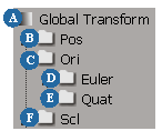
Object Velocity and Acceleration
If you get an object's velocity or acceleration values, the ICE tree calculates these values automatically. It does not read the values from the Global Transform property, and you do not need to compute velocity and acceleration in the Global Transform property editor.
Rotations can be represented by different data types. The data type that is called "rotation" consists of an axis of rotation, and an angle around that axis.
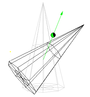
If you need to access the axis and angle as separate attributes, you can use the Rotation to Axis and Angle and Axis and Angle to Rotation nodes, or the Rotation to Scalar and Scalar to Rotation nodes.
There are other possible ways to represent a rotation:
You can convert between these representations using the nodes in the Conversion category. In addition, the Rotation category collects various nodes that are useful for rotations, including nodes that are also found in the Conversion, Constant, and Math categories.
You can calculate the result of composing two rotations (performing one rotation after the other) in several ways:
Note that multiplying two 3D vectors representing the Euler angles does not give the correct result (and actually has no geometric meaning). See Comparing Values.
Composing and Decomposing Transforms
You can use the SRT to Matrix node to compose separate position, rotation, and scale values into a 4x4 matrix representation of a transformation. Similarly, you can use the Matrix to SRT node to decompose a 4x4 matrix into position, rotation, and scale.
Both the SRT to Matrix and the Matrix to SRT nodes also work with 3x3 matrices. In this case, the matrix is assumed to represent rotation and scaling. You might need to pipe the output of the SRT to Matrix node through a 3x3 Matrix or 4x4 Matrix node (from the Constant category) to force the data type to be one or the other, if the data type is not automatically resolved by the rest of the ICE tree.
The Rotation output port of the Matrix to SRT node is polymorphic. It can return a rotation (axis and angle), a quaternion, a 3D vector containing the XYZ Euler angles, or a 3x3 matrix, depending on which nodes you connect it to. If necessary, you can plug it into a node from the Constant category to force a particular data type.
Converting Between Local and Global Reference Frames
You can convert between local and global positions. When you multiply a 3D vector by a 4x4 matrix, ICE assumes that the 3D vector represents a position in homogeneous coordinates and that the matrix represents a transform, and performs the calculation using special rules.
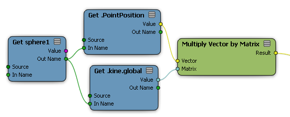
|
To convert local position to global, multiply the position by the global transform. |
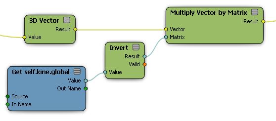
|
To convert global position to local, multiply the position by the inverse of the global transform. |
To convert between two different local reference frames, convert from the first reference frame to global coordinates and then from global coordinates to the second reference frame.
If you want to convert a 3D vector as a vector like PointVelocity rather than as a position like PointPosition, you should "zero out" the translation component of the transformation.
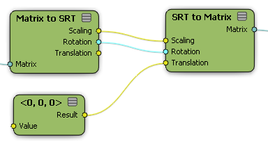
Remember also that you need to use a Switch Context node to combine positions or other 3D vectors from different contexts.