


The following steps describe how to create a capture area, and can give you an idea of the best location and a reliable way of testing the amount of magnetic interference.
Decide on the size of each square in your floor grid. Use tiles or tape on the floor to roughly mark each corner of a square grid. Each unit of the grid should use the same dimensions. A 12 x 12 foot grid is a good starting size, but this does not mean that your eventual capture grid is this large. If you have a small studio with only enough space for a 6 x 6 grid, measure this grid and mark the corners with tape.
Place the emitter beside your floor grid about 2 feet (60 cm) off the floor. Keep the emitter in mind when deciding on the placement of your floor grid.
All magnetic systems work by radiating a magnetic field using an emitter. The placement of the emitter is one of the most important aspects of creating a successful motion capture area.
Autodesk recommends that you place the emitter between 1.5 to 2 feet from the outer edge of the capture area, raised approximately two feet off the floor . You should place the emitter to take advantage of the largest possible capture area.
You should also place the emitter away from machines or other devices that may cause magnetic interference, such as computer monitors. If your studio is small, you can place the emitter within the capture area under an elevated stage or hang it from the ceiling.
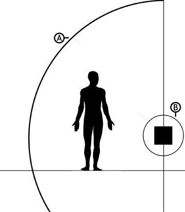
A. External Range limit B. Internal Range limit
The magnetic field is very strong; it is approximately 1.5 feet around all emitters. If the calibration pole or a wired performer stands within this area (Internal Range Limit), it is impossible for the position of the magnetic sensors to be accurately captured.
The magnetic field from the emitter also has a physical range (External Range Limit). If the calibration pole or a wired performer gets too close to the limit or moves outside the range, the position of the sensors cannot be properly captured.
Depending on the magnetic system and the number of emitters, the internal and external ranges may vary. Consult the documentation accompanying your magnetic device for more information on its capture range.
It is important to place the emitter at the proper height. A magnetic field is circular, with its longest range near its horizontal or vertical middle. For best results, place the emitter at a height where the longest part of the magnetic field rests over the capture area. Problems may occur during motion capture if an emitter is too high or too low .
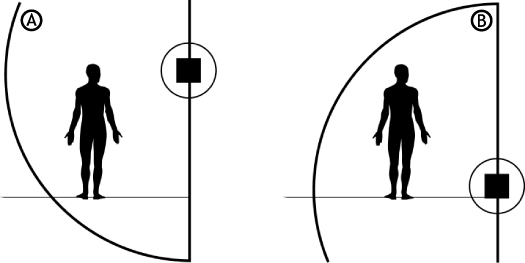
A. Emitter is too high. The performer’s feet may not be captured. B. Emitter is too low. The performer’s hands may not be captured if they are raised over the head. Even more may be lost if the performer jumps.
After placing the floor grid, building the calibration pole, and placing the emitter, test the capture area to make sure it does not contain too much magnetic interference.
To test the area, MotionBuilder must be running and the appropriate magnetic device must be added and set up. Then move the pole around the edge of the proposed capture area and around arbitrary locations within the capture area. While you move the pole, watch the Viewer window to see how sensors react to your proposed capture area.
For example, in the following figure, A represents an ideal capture, because the sensors are straight, and are exactly as they appear on the pole. In the same figure, B shows that the sensors are not completely straight, but would be easy to calibrate. In the same figure, C shows that the sensors are limited for a capture but they can still be calibrated. However, in the same figure, D shows too much distortion produced by sensor 8 (second from top) relative to sensor 7 (top sensor).

A. Ideal capture B. Suitable capture C. Limited capture D. Poor capture
 Except where otherwise noted, this work is licensed under a Creative Commons Attribution-NonCommercial-ShareAlike 3.0 Unported License