


In the Floor Contacts group of character properties, the Hands Floor Contact Setup folder let you adjust how hands make contact with the floor.
Corrects the hands but does not let you manipulate its finger base. This option is disabled by default when you create a character so that you can manually manipulate and animate each finger base.
When Automatic Finger Base is active, you cannot animate the finger base, but you can still keyframe the result positions provided by the floor contact.
To take full advantage of the solving from the finger base of each hand, it is recommended that when you create your model skeleton that the finger base should be the parent of each finger. The thumb should be parented by the wrist.
Lets you define which part of the hand should be treated as a pivot when the hands make contact with the floor. There are three options for the Hands Floor Pivot, described in the following table:
| Option | Behavior |
|---|---|
| Auto | The default option that averages the priority between the wrist and fingers. When the hand makes contact with the floor, the wrist is translated backwards and the fingers are pushed forwards. |
| Wrist | Gives the wrist priority and defines it as a pivot point for the hand’s floor contact. When the fingers make contact with the floor, they are translated forward to keep the wrist’s trajectory towards the floor constant. |
| Fingers | Gives the fingers priority and uses them as the pivot point. When the fingers make contact with the floor, the wrist is translated backwards to keep the fingers firmly planted on the floor. |
Lets you define the number and orientation of markers used to define the floor contact for the hands of your character. The following table illustrates the types of hand contact available:
| Option | Behavior |
|---|---|
| Normal | Six markers define each hand’s floor contact. The middle markers should define where the fingers begin. |
| Wrist | Four points define each hand’s floor contact. The hand markers display around each palm. |
| FingerBase | Four points define each hand’s floor contact. The hand floor contact markers display around each hand’s fingers. |
| Hoof | Four points define each hand’s floor contact, but the points are oriented at a 90 degree angle, letting you define the floor contact for animal types with hooves, such as horses. These contact markers allow for 180 degrees of movement. |
Lets you define how stiff and sudden the hand becomes as soon as any part of the hand contacts the floor.
For example, using MotionBuilder default settings but only adjusting the Hands Contact Stiffness to 100%, as soon as the fingers of the hand come into contact with the floor, the hand stops translating. At 50%, the hand translates gradually after coming into contact with the floor.
Lets you change the size of the contact markers that outline the hands. The center of the contact markers is the point used
for floor contact. Increasing the Hands Contacts Size only makes the floor contact markers more visible, it does not affect
the way the hands contact the floor. To view the contact markers for both hands and feet, select  > Show/Hide > Floor Contact from the Character Controls window.
Each setting in the Hands Contacts Position folder lets you define the contact region for the hands numerically. You can also change the region by selecting the hand floor contacts in the Viewer window and translating them.
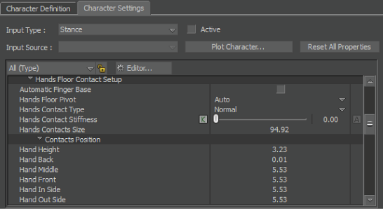
Hands Contacts Position folder and settings
Each Hand Contacts Position setting defines a different aspect of the hand contact area. These settings are described in the following table:
| Setting | Description |
|---|---|
| Hand Height | Defines the bottom of the model’s hand. Change this setting until all markers are at the bottom of a model’s hand. |
| Hand Back | Defines the back edge of the model’s hand. Change this setting until the back markers are behind the hand. |
| Hand Middle | Defines the middle of the hand, where the fingers bend. Adjust this setting until the middle markers are where the fingers bend. |
| Hand Front | Defines the front part of the model’s hand. Change this setting until the markers are in front of the hand. |
| Hand In Side | Defines the interior of the hand. Adjust this setting until the markers are at the interior of the hand. |
| Hand Out Side | Defines the exterior of the hand. Change this setting until the markers are at the exterior of the hand. |
 Except where otherwise noted, this work is licensed under a Creative Commons Attribution-NonCommercial-ShareAlike 3.0 Unported License