Creates a surface by sweeping a profile curve along a path curve.
Flat maintains the orientation of the cross section as it moves along the extrusion path.

Tube sweeps the cross section along the path with the reference vector staying tangent to the path.

Distance extrudes the profile in a straight line. Do not select a path curve when you turn on this option. When Distance is on, the options window provides extra options: Extrude Length, Direction, and Surface Degree.
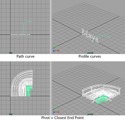
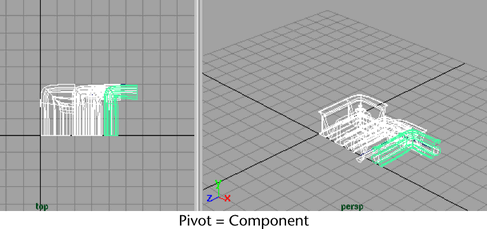
The Pivot options are available only if you set the Style to Tube. If you select At Path as the Result Position, you can choose the profile curve then position it at the pivot point on the extrusion path.
If you select Closest End Point, the path end point closest to the center of the bounding box of the profile curves is used. This end point is used as the pivot point for all the profile curves. If you are doing a multiple extrusion, the resulting surfaces are offset from the path.
If you select Component, the pivot point of each individual profile curve is used to extrude the profile curve. The extrusion occurs along the components of the profile curve.
In the following example, Result Position is set to At Profile and Orientation is set to Profile Normal. The path curve is moved and rotated to match the profile curve. This is the default setting.
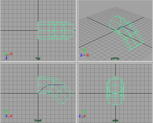
In this following example, Result Position is set to At Path and Orientation is set to Path Direction.
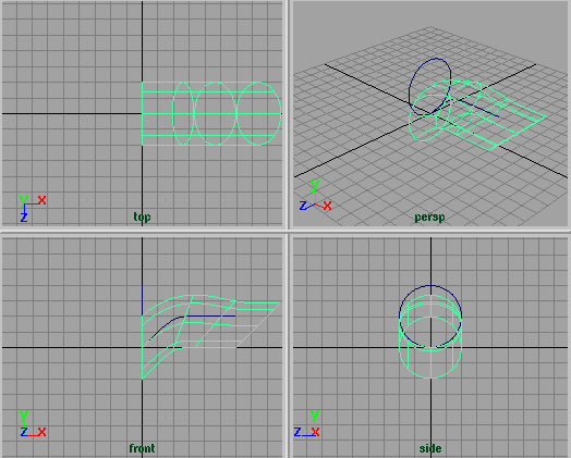
In the following example, Result Position is set to At Profile and Orientation is set to Profile Normal. The profile curve is moved and rotated to match the path curve.
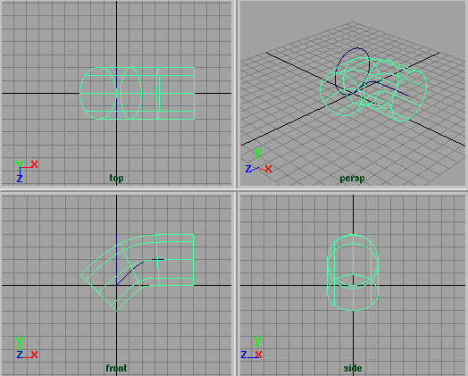
Complete extrudes the entire profile along the entire path.
Partial extrudes only part of the profile along part of the path. If construction history is turned on, this creates a subCurve node that you can edit to change the extruded surface. See Editing the extruded surface using manipulators.
Note that the Profile Curve and Path Curve boxes let you access the input curves as well as statistical information about these curves. Click the arrows beside the boxes to select the input curves. Click the tab to open the Attribute Editors for them.
Editing the extruded surface using manipulators
After you extrude the surface, select the surface, display the Channel Box, and select the Show Manipulator Tool. Click each of the subCurve nodes in the Channel Box to display the different manipulators available.
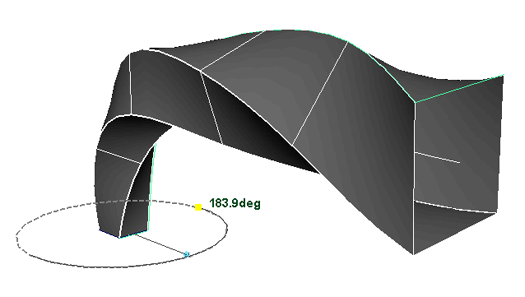
Experiment with the manipulators to see their effect on the surface. They let you change the length and sweep of the extrusion.