Lists attributes on the selected object. Tabs across the top of the Attribute Editor let you select nodes connected to the shown node.
While the Channel Box provides a more compact view of keyable attributes, the Attribute Editor gives you full graphical controls to edit attributes rather than just text boxes. There are ramp and graph graphical controls. For more information, see Attribute editor graphical controls.
You can set an option in Window > Settings/Preferences > Preferences to have the Attribute Editor open in a window instead of the side panel.
Loading object attributes into the Attribute Editor
Loading attributes into the Attribute Editor makes them available to view or edit. There are three ways to load object attributes into the Attribute Editor:
Loading attributes automatically
When you select an object, its attributes are automatically loaded into the Attribute Editor where you can view and edit them. Each node of the selected object automatically appears as a tab. This is the default method.
To automatically load attributes for selected objects
The color of the attribute box changes depending on its state. For more information, see Channel Box colors.
This option displays only for attributes that are connected to keys or textures. Select the Ignore when Rendering option to ignore the connection when rendering. If the attribute has a map button, the button changes to indicate that the connection is ignored.

Select the Don’t Ignore when Rendering option to render with the set connection. For details, see the Rendering guide.
Turn on to provide a different/more user-friendly name that will be used when viewing this attribute in the Attribute Editor or Channel Box.
(A default nice name will be created if your attribute name is intercapped (that is, setAttributeBlackOrWhite becomes Set Attribute Black Or White).)
The nice name is only stored in the file if the Override nice name box is checked; otherwise, it's computed from the long name. This may insert multi-byte characters into a .ma (Maya ASCII) file if the nice name is in a multi-byte language such as Japanese.
Defines the following attributes:
For more details on these attribute types, see Channel Control Editor.
Turn on to create a corresponding initial state attribute for the added attribute. Without this corresponding attribute, you can’t save a particle object’s current attribute values for initial state usage. You must write a creation expression if you decide to initialize the custom attribute’s value upon rewinding the animation. If you know you’re going to write a creation expression for a custom attribute, you can set Add Initial State Attribute to off when you add the attribute. Otherwise, set Add Initial State Attribute to on whenever you add a custom per particle attribute.
For scalar attributes, Minimum and Maximum set the lowest and highest values you can enter for the attribute in the Attribute Editor or Channel Box. Default sets the default value for the attribute.
When you're adding a new Enum attribute, you need to define the list of acceptable strings. There are two default strings, “Green” and “Blue”, in the Enum Names list that you can change. To change, select Green or Blue and then enter the new string in the New Name text box. To add a new string, click the blank entry below the last list item and type the string in the New Name text box.
The following list of names are reserved internally for (dynamic) shading attributes. You may use these names for custom attributes, but beware they may produce unexpected results in the shading network. For example, during shading the uvCoord value is provided, therefore ignoring your custom uvCoord attribute value.
Attribute editor graphical controls
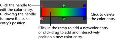
There are two common graphical controls that appear in the Attribute Editor for certain attributes: ramp and graph.
Each color entry in a ramp has a circular color handle above the ramp, and a square color icon below the ramp. The active color has a white border around its color handle and icon. Ramps can be used for many types of gradients, including transparency, color, and so on.

For more details about ramps in shading, see Ramp Shader.
The graph control has handles which you can drag in the graph area to set position-value pairs. The active point has a white border around its handle and icon. Graphs can be used for many types of attributes where value changes per position, including paint effect settings, fluid settings, and so on.

Opening the ramp and graph controls in a separate window
Click the arrow on the right side of the control to open the ramp or graph control in a larger window.
For the graph control, you can edit the interpolation method, selected value, and selected position. For the ramp control, you can edit the interpolation method, the selected color, and the color entries. In addition, you can turn on turn off Vertical to switch between a vertical or horizontal layout.
Checking the vertical box alters the size of your ramp. Once you check the vertical box, the ramp or graph automatically adjusts to a suitable size.
When you save your scene, Maya also saves the layout that you have chosen for your control.