


The Blind Data Editor lets you create, apply, edit, and view blind data.
If the selected blind data type already has a particular association type assigned to it, then this option is available and the data will only be applied to that component type (or, if the type is object, to the whole object). Otherwise, if the type was Any, this option is not available and you should select the association type you want to apply your data to. The default is face.
Selected components are converted to the Assoc Type before the data is applied.
If the data types of the selected blind data type are not all either int or double, this menu is unavailable. Possible values are Absolute, Offset, and Scale.
Selects the Edit > Paint Selection Tool and opens the Tool Settings window. This tool only works if you have a blind data type selected and if the association type is face or vertex. The component pick mask is switched to the association type selected for this blind data type, and the data is applied on every mouse release.
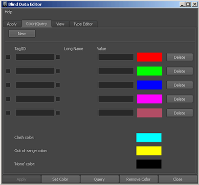
Use this tab to false color and query polygonal objects and components based on criteria you set up. There are several levels through which you can look at the data.
The first is a high level view of what components or objects have the specified blind data assigned to them, regardless of value.
The colors show the sequence of queries that were performed, and do not get updated by subsequent changes to blind data. If the object’s topology changes, colors may no longer be accurate.
In the following illustration, Set Color goes through the selection list and colors components that have floorType blind data red, wallType blind data green, and ceilingType blind data blue. If any components have two or more of the specified types assigned, the components (or objects) are colored with the Clash Color, in this case, light blue. Components that have none of the specified types are colored with the None color, which is black in this case.
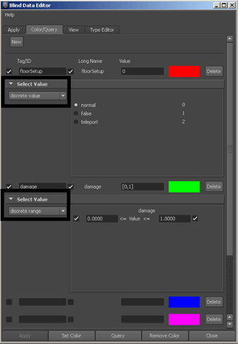
Select this option to color or query a range of values for a particular type.
In the following illustration, components with the blind data type floorType with a value of 0 (corresponding to preset: normal) are colored red. Components with blind data type damage and values between 75 and 100 are colored green. Components with both floorType and damage blind data are colored with the Clash color.
Integer or double data can also be colored with grayscale values. Select continuous from the drop down menu, and select min and max values and colors to use in coloring the data.
In the following illustration, the blind data type floorRough is displayed. Components which have a value of 0 are colored black, those with values of 1 are colored white, and those in between will have the appropriate grayscale. Values less than 0 or greater than 1 are colored yellow, the Out of Range color. The None color is blue to differentiate between components with 0 floorRough and components that have no floorRough assigned at all.
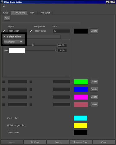
When using the continuous type, query works as if discrete range were selected; any components that have blind data with values between the min value and the max values are added to the selection list.
The Blind Data Editor will not properly handle false coloring and querying of more than one blind data type with the Continuous type enabled. The Blind Data Editor also will not handle combinations of Discrete Value colors/queries (including unsigned color/query actions) and Discrete Range colors/queries - if a specific value is required in combination with a range, use that value for both the Min and Max in the discrete range section.
You can also color and query with the hex type if the blind data type selected consists of hex data.
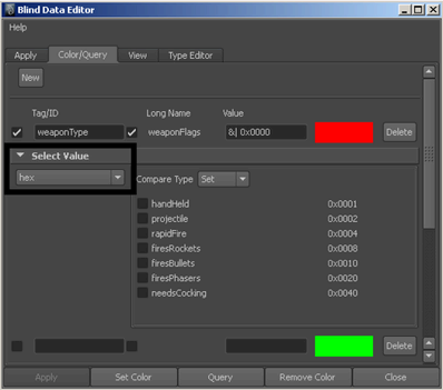
When the selected Compare Type is Set, components with the selected value(s) set are colored or selected. If it is Not Set, only components with the value not set are colored or selected. If set to Equal, only values which equal the selected value are colored or selected.
Describes what the blind data is attached to. Valid choices from this editor are Face, Vertex, Object, or Any. If you select Any you have to choose what you want to apply the data to when you are applying it. If you select Face, Vertex, or Object, the data is assigned only to that type of component or object (and selected objects/components are converted to this type).
If the component type you are going to be applying this data to is always going to be the same, it’s a good idea to select it here so that Maya will know how to treat your selection when applying, coloring, or querying components.
Type the short name for the attribute you’re defining, such as “msg” for message. This name must be 3 characters or less and can contain, but not start with, numeric characters.
For object blind data, choose unique long and short names for the blind data type, making sure they are different from any attribute name on the object to which you are going to apply the blind data. For component blind data, the names must be unique within the DG node.
To see all the long names of attributes on a shape, type:
listAttr pPlaneShape1;
To see all the short names of attributes on a shape, type:
listAttr -sn pPlaneShape1
This option is available only if you have a numeric data type selected (double, int, or hex) and if Free Set is turned on. Turn on Ranged to restrict the data to an upper and lower range. When you turn it on, the Min and Max boxes appear for you to specify the upper and lower range.
You use Presets to set up values you can quickly select by name instead of having to know which values to use. They provide a means for enumerating integral or (in the case of the hex type) flag values, that let you quickly set frequently-used data and, if Free Set is turned off, restricting what values you can apply to data.
Click this button to create a new preset; when you do, several input boxes appear. There is one box for the Name of the preset and one box for each attribute in this blind data type. Click Delete to remove presets you do not want.
Once you have entered all of the data, click the Save button to save this blind data type to the scene so that you can apply data using it as a template.