


Setting Camera Properties
for Manual Tracking
Before analysing the manual 3D motion and tracking, you may want to define your camera. The camera represents the device used to acquire the sequence of images you are tracking. Typically, when you load a clip, the camera position, field of view (FOV), and point of interest (POI) are assigned to each frame in the clip by default. For the purposes of 3D tracking, a camera is characterized by its internal properties: the principle point, the pixel aspect ratio, the focal length, and the non-linear distortion.
The manual 3D tracker handles most camera motions including zoom, even when only a small change in position or direction of an object is caused by a change in the point of observation. For each camera parameter, you can choose to let the 3D tracker calculate the value automatically or you can specify the value yourself.
If you already have information about the camera, you can specify this information before using the manual 3D tracker. When you provide information about the camera, the calculation and rendering is much faster than when the tracker has to calculate the properties itself.


(a) Film Back box (b) Aspect Ratio box
| Use: | To: |
|---|---|
| Film Back box | Specify the image resolution. |
| Width field | Specify the width of the film back. |
| Units box | Identify the unit of measure: inches or millimeters. |
The image resolution values change according to the Film Back settings.
| Select: | To: |
|---|---|
| Constant Initialised | Let the 3D tracker estimate the value, starting from an approximate value that you specify. The value remains constant for all the frames in the sequence. |
| Constant Unknown | Let the 3D tracker compute the value and keep the value constant for all the frames in the sequence. |
| Variable Initialised | Let the 3D tracker estimate the value, starting from an approximate value that you provide. The value can change across the frames. |
| Variable Unknown | Let the 3D tracker compute the value with no input from you. The value can change across the frames. |
| Fixed | Use the value you provide with no modifications made by the 3D tracker. |
Setting focal length constraints tells the manual 3D tracker that the focal length is constant throughout the clip sequence. If you know the film back and the camera, you can allow the 3D tracker to calculate the focal length automatically by setting it to Constant Initialised.
The film back sets the field of view and might change the focal length and distance of the camera from the scene; however, it should not affect the quality of the shot.
Viewing the scene from the Side view lets you see the frustum more clearly. In this way you can view the camera and the scene.
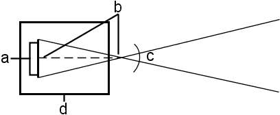
(a) film back (b) focal length (c) field of view (FOV) (d) camera
The manual 3D tracker uses lens distortion so that tracking points that are positioned far from the principle point—or the centre of the image—are taken into account. The distortion is a radial value measured from the centre of the principle point.
If the footage you are tracking contains a lot of lens distortion—perhaps due to a very wide angle lens—set the distortion with respect to the principle point so that track points in distorted areas are tracked accurately by the manual 3D tracker.

(a) Principle point (b) Distortion point
| Select: | To: |
|---|---|
| Fixed | Specify a principle point whose position does not change. Select this when you know the position. |
| Constant Initialised | Specify an estimated value for the principle point whose position does not change. Select this if you do not know where the principle point is, for instance, if the image is cropped. |
| Constant Unknown | Let the 3D tracker determine the principle point. Select this only after you analyse the 3D track using Constant Initialised and you are not satisfied with the result. If you are still not satisfied with the result after using Constant Unknown, try setting a few track point relations and use Constant Initialised again. |
A value of 0,0 corresponds to the lower-left corner of the image.
| Select: | To: |
|---|---|
| Fixed | Specify a distortion whose value does not change. |
| Constant Initialised | Specify an estimated value for the distortion that does not change. |
| Constant Unknown | Let the manual 3D tracker determine the distortion. |
