Distort is accessible from both the Desktop and Batch.
In Batch, you can create a more convincing morph, for example, by animating colour transitions between the first and second clips using Colour Corrector nodes.
To access the Distort menu from the Desktop:


| Select: | To load: | To produce: |
|---|---|---|
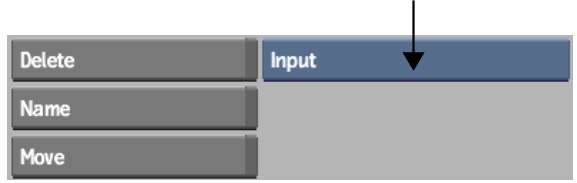
| Input | One input clip only | A warp of a single clip. |
| Input Matte | An input clip with its matte | A warp of a single clip using a matte over a black background. A warped matte is also produced. |
| Input Matte Bg | An input clip with its matte, as well as a background | A warp of a single clip using a matte over a background clip. A warped matte is also produced. |
| Input1 Input2 | Two inputs | A morph from one clip to another over a black background. |
| Input1 Input2 Bg | Two inputs, as well as a background | A morph from one clip to another over a background clip. |
| Input1 Input2 Matte1 Matte2 | Two inputs with their respective mattes | A morph from one clip to another over a black background. A morphed matte is also produced. |
| Input1 Input2 Matte1 Matte2 Bg | Two inputs with their respective mattes, as well as a background | A morph using two clips and their mattes on a background clip instead of on black. A morphed matte is also produced. |
For example, if you selected Input1 Input2 Matte1 Matte2 Bkg to morph between two clips, select clips as follows:
To access the Distort menu from Batch:
The Distort menu appears. The Distort node outputs a warped or morphed result and a warped or morphed matte.
The Distort controls are described as follows.
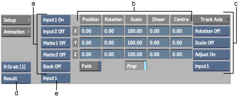
(a) Clip Display buttons (b) Axis controls (c) Axis Stabilizer controls (d) View box (e) Input box
Clip Display buttonsControls which clips, of those you load into Distort, are displayed. Use the Clip Display buttons to produce various effects, or to toggle on or off clips and mattes to facilitate your work.
Axis controlsEdits the axis position, scale, and shear value of a spline.
Axis Stabilizer controlsGives access to the Stabilizer, for automatically tracking motion in the axis.
View boxSets the view in the image window. Two views available from this box, Input and Matte, each correlate with two distinct views, Input1 and Input2, or Matte1 and Matte2. You toggle between the input or matte views using the Input box.
Input boxToggles between the Input1 and Input2 clips. If Input is selected in the View box, this box toggles between Input1 and Input2. If Matte is selected in the View box, this box toggles between Matte1 and Matte2. If Result is selected in the View box, this box toggles between showing the splines for Input1 and Input2 drawn on top of the result.

(a) Warper button (b) Interpolation field (c) Spline Display controls (d) Refining controls (e) Shape Stabilizer controls (f) Blend field (g) Link box
Warper buttonChoose to display the Warp or Morph menu.
Interpolation fieldControls the percentage the Input1 spline mixes with the Input2 spline when source splines are linked for source interpolation. You independently set an interpolation value for each set of linked Input1 and Input2 source splines.
Blend fieldUse to blend between the Input1 and Input2 clips when morphing.
Source buttonDisplays source splines for manipulation. Also use to display the unwarped input clip.
Source Show buttonDisplays source splines for reference when working with destination splines.
Source colour potSets the colour of all source splines.
Destination buttonDisplays destination splines for manipulation. Also use to display the warped input clip.
Destination Show buttonDisplays destination splines for reference when working with source splines.
Destination colour potSets the colour of all destination splines.
Correspondences buttonClick to display correspondence points and connector lines, which indicate how the source spline maps to the destination spline for both warps and morphs. You can add, edit, animate, and delete correspondence points. The more correspondence points a spline has, the greater effect it has on the overall warp.
Active button Allows greater control over an animated spline by toggling selected vertices on and off.
Lasso Fit fieldAdjusts the number of vertices in freehand segments of a spline. Increasing the value decreases the number of vertices, while decreasing the value increases the number of vertices. Only segments of the spline drawn using freehand mode are affected, while segments created by simple clicks remain unaffected. The Lasso Fit parameter loses its influence over freehand segments of a spline if you edit vertices.
Link boxControls whether source and destination splines are linked together or manipulated independently. Set this to Lnk Src & Dst to keep the source and destination splines linked as you draw and animate the source spline. Set this to Enable Warping to control the destination spline independently to create a warp. You can also independently link and unlink the axis nodes that are the parents of a source spline and its corresponding destination spline.
Toggle Input buttonChanges a spline from an Input1 spline to an Input2 spline, and vice versa. This is useful when you have animated a spline on one input and wish to apply it to the other.
Iterations fieldIf Z-mode is disabled, the maximum distance of the distortion is limited to avoid overlapping. When there is a large distance between a source and destination spline, you will achieve better results by increasing the number of iterations. For smaller warps or morphs, there is no advantage in using a greater number of iterations—it will increase processing time unnecessarily.
Z-mode buttonEnable Z-mode to allow overlapping in your image to create 3D-like effects where parts of the image are “pulled” over other parts.
Range fieldDetermines how big a region is affected by the warping effect. The greater the value, the larger the portion of the image affected. A value of 100% affects the entire image, a value of 33% affects one-third of the image, for example.
Weight fieldSets a relative weight to the selected spline to control its influence. For example, you can set a higher weight on a spline in an area of the image that you do not want to move.
Resolution field Adjusts the pixel resolution of the clip being warped or morphed. A lower pixel value increases resolution. A lower pixel resolution creates warps and morphs that better follow the contours of the distortion splines, although it can slow down system performance.
Shape Stabilizer controls Gives access to the Stabilizer, for automatically tracking motion in the source clip and using this data to animate your spline.


