The Distort schematic uses nodes to represent all the splines in the scene. The schematic shows relationships between source and destination splines, and between splines applied to the Input1 and Input2 clips.
Use the schematic to control all the splines in the scene, set parent-to-child relationships among nodes, as well as to select splines more easily.
You also use the schematic to link Input1 and Input2 source splines to create morphs using source interpolation. See Linking Source Nodes.
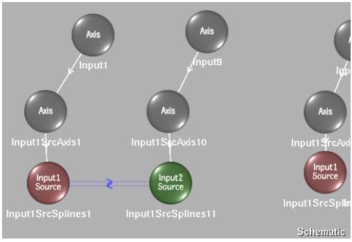
When you add a spline to the Input1 clip, for example, the following spline node tree appears.


(a) Spline node tree representing corresponding splines added to Input1 (b) Axis node for an Input1 spline: the parent of corresponding source and destination splines (c) Axis nodes for each spline (d) Spline nodes for corresponding source and destination splines added to Input1
Each spline added to an input clip results in its own spline node tree in the schematic, with its own corresponding source and destination splines.
You can change an Input1 spline to an Input2 spline or an Input2 spline to an Input1 spline using the Toggle Input button. See Toggling Spline Nodes from One Input to Another.
Visibility of the splines is controlled from the Warp or Morph menu using the Spline Display controls. When you toggle between the Input1 and Input2 clips with the Input box, splines are hidden for the inactive clip, which is also reflected in the schematic.
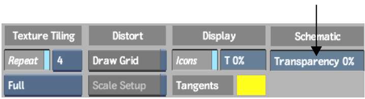
You can also set the transparency of the schematic. This is useful if you want to dim its display so as not to interfere with the main focus of your work.
To set the transparency of the Distort schematic: