You must select a node before you can edit any of its properties. Conversely, selecting an object in the scene of some modules, for example, an axis in the Action scene, also selects the corresponding node in the schematic. A menu appears for each node selection.
You can select a single node or a combination of nodes. A branch is the structure of a parent node and one or more child objects. A tree is the structure of all connected clips and nodes.
Action has specific node selection rules depending on what type of object is selected. See Using the Schematic and Menu Tabs.


| To select: | Do this: |
|---|---|
| One node | Choose Selected from the Selection Mode box and then click the node. |
| A branch (a node and all of its children) | Choose Branch from the Selection Mode box and then click the first node (the parent node) in the branch that you want to select. |
| All nodes in schematic | Choose All Nodes or All from the Selection Mode box and then click any node. |
| An entire process tree (Batch and Modular Keyer) | Choose Tree from the Selection Mode box and then click any node in the tree that you want to select. |
In the following Distort scene-based schematic, the selected node in the hierarchy is outlined in yellow, and the other nodes that are part of the selection are outlined in white. Branch was chosen from the Selection Mode box.
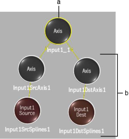
(a) Selected (parent) node (b) Selected nodes in branch
In the following example, the selected node in the Batch flow graph schematic is outlined in yellow, and all nodes before (upstream of) the selected node are outlined in white. Branch was chosen from the Selection Mode box.
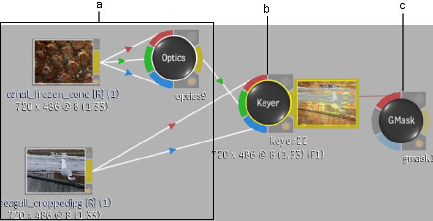
(a) Nodes in branch upstream of selected node (b) Selected (parent) node (c) Node downstream in branch is not selected


