You can import 3D polygon objects such as 3ds Max files, FBX files, Wavefront files, Inventor files, garbage masks, and Paint geometry. 3ds Max files contain object data, specifically, texture and materials. The FBX format acts as the intermediary between different file types. Files can be exported from another product to the FBX format and then imported into Flame.
Paint geometry files are created by the Flame Paint module. If you want to work with polygon geometry in Action, import Paint geometry. Action ignores its animation and attributes, such as its colour, outline, and gradient. For example, in Paint, if you create a blue polygon, animate its scale, and save it as geometry, it is imported in Action as a white polygon with no animation.
You can import a 3D model into one or several geometry nodes. You can also import multiple 3D models into a single animated geometry node.
The Import menu and file browser appear.


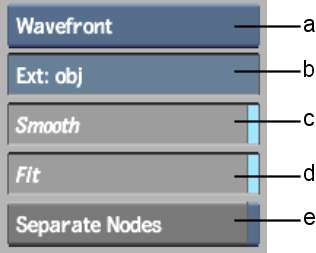
(a) Import Type box (b) File Extension field (c) Smooth button (d) Fit button (e) Separate Nodes button
The Import controls are described as follows.
Import Type boxSelect the 3D model type to import: FBX, Wavefront, Inventor, 3DStudio, FBX, Gmask, Paint, or Photoshop.
File Extension fieldDisplays the default extension for the file type selected in the Import Type box. By default, Wavefront files have .obj, Inventor files have .iv, FBX files have .fbx, and 3D Studio files have .3ds as their file extensions.
Smooth buttonEnable to build normals for the 3D model. Enable if you are importing polygons that do not have normals.
Fit buttonEnable to scale the imported model to fit into the current frame. When this button is disabled, the imported model maintains the same size in which it was created.
Separate Nodes buttonEnable to create individual nodes for all 3D models contained in a file.
When this button is disabled, the 3D model is added to the scene with its own axis.
Rotate Axis buttonEnable to rotate the imported 3D model by 90 degrees on the X-axis so that it is compatible with Action's coordinate system. This button is enabled by default, and appears only when 3DStudio is selected as the import format.
The 3D model and axis is added to the scene. For 3DStudio models, the axis is centered in the bounding box of the model.
You can change the 3D model's colour, specular highlight, shine, and other material properties. See Working with 3D Geometry.
To import multiple 3D models into an animated sequence:
The selected 3D models are loaded to the same line in the Media list.
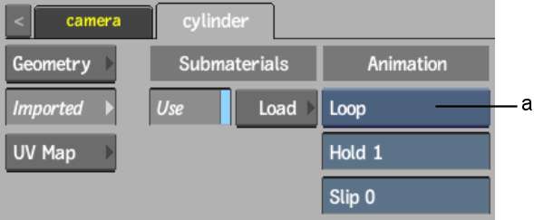
(a) Animation Mode box
| Select: | To: |
|---|---|
| Loop | Play in a continuous loop. |
| Once | Play once. The 3D geometry is no longer displayed. |
| Last Still | Play once, and hold the last frame. |
| Timing | Animate according to the timing in the animation channel. |
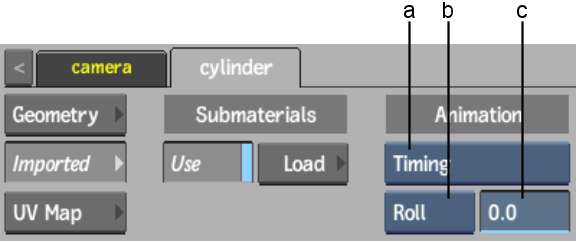
(a) Animation Mode box(b) Timing Range option box (c) Frame Timing field
| Select: | To: |
|---|---|
| Roll | Roll over the Frame Timing value. |
| Cut | (Geometry is not displayed.) |
| Round | Display the first or last geometry (with this option, you can select the first and the last geometry of your animation). |


