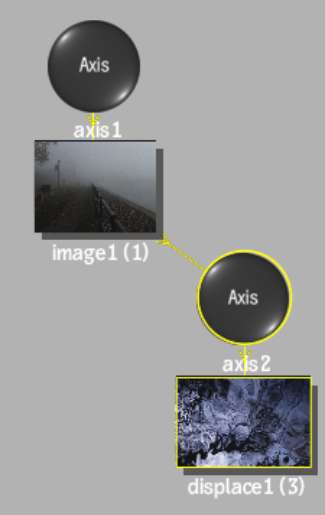
Use displacement mapping to create a 3D model from a 2D surface. The values of a selected colour channel in the displacement source clip are used to create a displacement map. When the displacement map is applied to the surface, the pixels of the surface are displaced along the positive or negative X, Y, and/or Z axes. Displacement mapping uses the media’s matte clip, so you can turn the matte on or off to get the desired effect.
The displace object is added to the schematic with its own parent axis. The new axis is the child of the selected surface or geometry. In Schematic view, the number in brackets next to the name of the displace node indicates the media used for the displacement.


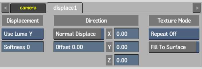
Use the following Displace menu settings (in any order) to get your desired effect.
Channel boxSelect a colour channel to calculate the displacement map.
Softness fieldDefines the level of rounding off, or softening of the spikes that result from colour values in the image that vary from pixel to pixel in the displacement map.
Softness rounds the edges of the displacement. The larger the softness, the smoother the displacement. Softness also affects rendering; the larger the softness, the longer it takes to render.
Normal Displace buttonEnable to displace bilinear and bicubic surfaces according to their normals. For flat surfaces, disable to displace in the X, Y, and Z directions.
Offset fieldApplies an offset to the displacement of X and Y.
Displacement axesSpecifies the amount of displacement in pixel units along the X, Y, and Z axes. Use positive values for displacement on the positive axis, and negative values for displacement on the negative axis.
Repeat mode boxSelect how the displacement map pattern is repeated on the surface.
Fill to Surface buttonEnable to resize the displacement map to the resolution of its parent surface.
The following figure illustrates a possible use of displacement mapping and shows the difference between displacing with and without softness.
Original image |
Z-axis displacement (60) using the luminance channel (Y) and a softness of 0 |
Z displacement (60) using the luminance channel (Y) and a softness of 12 |