Earlier in the lesson you split the helmet mesh by inserting edge loops across the mesh. You can split localized areas of
a mesh using the . When using the tool you draw a line across the faces to indicate the location for the split. You'll begin by vertically
splitting the face shield.
To split the face shield vertically
- Select the helmet mesh.
- Select .
- Tumble the camera in the perspective view so you can view both the upper inner edges of the face shield as well as the lower
inner edges.
- Click the top inner edge of the face shield to indicate the start of the split (see image below).
- Click on the lower inner edge of the helmet mesh to indicate the end of the split (see image).
- Press the y key to split the face.
- Continue to split the face shield vertically at the other locations specified in the image below. Remember to press the y
key after each split.
When you are finished the n-gon for the face shield will be split into four new polygons.
You can also split the face shield horizontally. This will give you more control over its shape afterwards.
To split the face shield horizontally
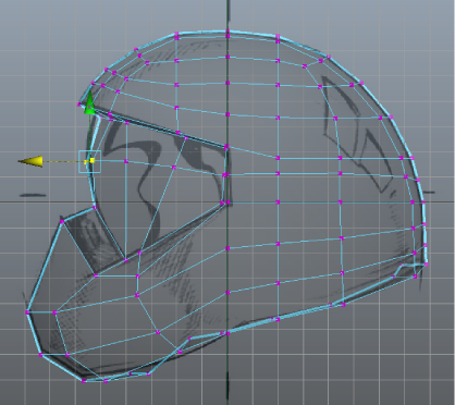
- In the perspective view, with the still active, click the inner side edge (see image) to indicate the start location for the horizontal split.
- In the side view, click the front vertical border edge of the face shield (this border edge lies on the axis of symmetry)
and release the mouse button at the mid-point along the edge where the vertex naturally snaps (as if a magnet were attracting
it towards that location).
- In the perspective view, rotate the helmet and click its back vertical border.
- Press the y key to split the faces.
Note
When you split across multiple faces at the same time you only need to click an edge to indicate the start point for the split
and on a second edge to indicate the end point. The automatically splits the edges in between.
- Press the q key to quit the .
In the next steps you'll reposition some of the vertices along the horizontal split to make the face shield protrude outwards
a small amount.
To adjust the shape of the face shield
- In the side view, select the middle two vertices at the front of the face shield and use the to move the vertices outwards (+Z) a small amount (see image).
- In the perspective view, select the remaining middle vertices on the face shield one at a time and reposition them outwards
a small distance using the with the option set to .
Tip
Tumble the perspective view so you can see the relationship between the vertices as you move them outwards.
- Reset the 's to before continuing to the next steps.
To create the diagonal grill vents on the lower front of the helmet you’ll insert edges on the face, reposition some of the
vertices, and then extrude some of the faces.
To insert multiple edges for the diagonal grill vents
- Select >
 .
.
- In the window, set the following:
These settings let you insert four evenly spaced edges on the face where you want the grill vents to appear.
- In the perspective view, click the border edge of the face where the grill vents will appear and then click the edge directly
opposite that border edge (see image).
- Press the y key to complete the edge loop insertion
- Click off the mesh to deselect the edges.
- Press the q key to exit the tool and return to selection mode.
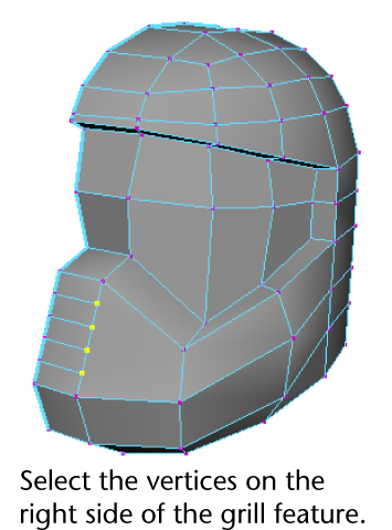
To make the grill vents appear diagonally you’ll select the vertices on the right side and then slide them downwards using
the .
To move vertices along an edge using the Move Tool
- Right-click the helmet mesh and change the selection mode to .
- Select the vertices on the right side of the grill feature (see image below).
- Double-click the icon to display the ’s settings editor.
- In the s’ settings editor, click the button.
The vertices appear unselected temporarily. The expects you to select an edge it will reference for the axis of movement.
- Click an edge that is on the same line of the edges as the vertices you selected.
The manipulator appears and is aligned to the edge you selected. The vertices appear selected again indicating that the is now set to move those vertices along the axis defined by the edge you selected.
- Drag the red arrow on the manipulator downwards to move the vertices so that the shape of the faces for the grill are more diagonal (see image).
Note
Make sure you do not move the vertices so that the lowest vertex touches the corner vertices or you’ll create an edge that
has zero length.
- Click off the mesh to deselect the vertices.
- Before proceeding to the next section, double-click the and reset the tool settings by clicking the button.
To make the grill vents three-dimensional, you’ll extrude some of the thin diagonal faces inwards.
To extrude the faces for the grill feature
- Right-click the helmet mesh and change the selection mode to Face.
- Beginning at the bottom of the grill feature, shift-select the two diagonal faces as indicated in the image below.
- Select .
The manipulator appears.
- Drag the blue arrow on the manipulator towards the helmet a short distance to create the two recessed vents for the grill.
- Press the q key to quit the feature.
- Shift-select the two side faces on the grill vents that lie on the axis of symmetry and delete them (see image below). These
faces will not be required when you create the opposite half of the helmet.
- Save your work before proceeding to the next section.
To prepare for the next part of the tutorial, open the Helmet4.mb scene () or continue working with the current scene.
 Except where otherwise noted, this work is licensed under a Creative Commons Attribution-NonCommercial-ShareAlike 3.0 Unported License