You can create new polygon components from existing ones using the feature (). When you extrude a polygon component (for example, a face, edge, or vertex), you create additional polygon components from
the ones you selected. Using the feature you will:
- Create the lower front region of the helmet by extruding the polygon face you created in the last section of the lesson.
- edges around the face shield and along the lower bottom edge.
To extrude the polygon face for the lower front region
- Enlarge the scene view to a single perspective view.
- With the polygon face still selected, choose .
The extrude manipulator appears on the selected face.
- In the perspective view, enter a value of 1.5 into the field to extrude a section of mesh:
- Press the g key to extrude again.
- Enter a value of 2.0 in the field.
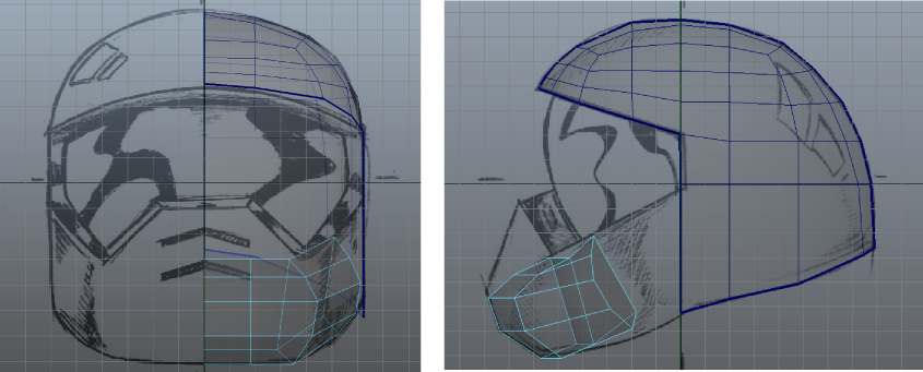
- Click the large blue circle that surrounds the manipulator to display the rotate manipulators and then drag the green circular
manipulator to rotate the angle of the extrusion to match the angle in the reference sketch (see image). You can also open
the and set to -26.
- Press the g key once again to create a third extruded region.
- Enter a value of 3.0 in the field.
- Enter the following values in the to adjust the angle of the extrusion:
- : 12
- : -30
- : 16
- : 0.5
- : 1
- : 1.3
- You may also want to view the extrusion from either the front or side view to ensure your extrusion doesn’t extend outwards
more than the side region.
- Save your work.
To delete unwanted faces on the extruded mesh
- Tumble the perspective view until you can view the inside of the lower front region (see image below).
- Select the faces that appear on the inside of the mesh you just extruded, including the faces on either end of the extrusion.
These faces were required for creating the extruded portions of the lower region but are not needed beyond this point.
- Press the Delete key to delete the selected faces.
When you are finished, a gap will exist between the last extruded segment of the lower region and the helmet mesh.
You’ll combine these separate meshes together and then create a mesh that bridges between them in the next section of the
lesson. To prepare for the bridge, you need to extrude more edges on the helmet mesh so that the number of edges match when
you create the bridge.
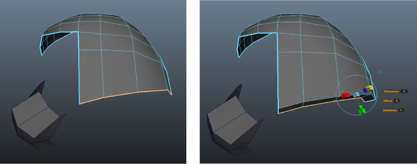
To extrude the bottom edges of the helmet mesh
- In the perspective view, select the lower edges of the helmet mesh using .
- Select , then enter a value of -1.0 in the field that appears.
To extrude top and side edges for the face shield
- In the perspective view, select the upper and side edges on the helmet mesh using (see image below).
- Select and then enter a value of -1.0 in the field that appears.
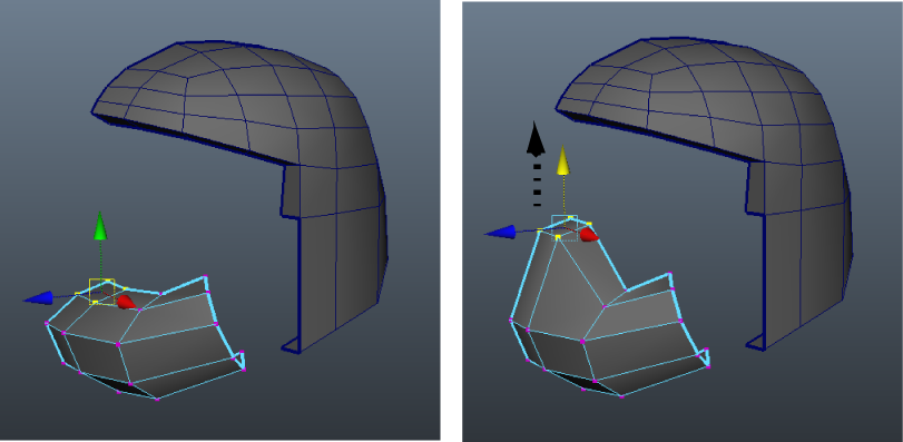
To move vertices on the lower front region to match the reference sketch
- In the perspective view, right-click on the helmet and select vertex mode to change the selection type to vertices.
- Select the four vertices on the lower front region of the helmet that are near the axis of symmetry (see image below) and
using the , move the selected vertices upwards by dragging the green arrow on the manipulator so that the lower front region of the helmet matches the reference sketches as they appear in the various orthographic
views.
- Adjust any vertices on the lower region that may require minor repositioning by selecting and moving them as necessary.
To prepare for the next part of the tutorial, open the Helmet2.mb scene file () or continue working with the current scene.
 Except where otherwise noted, this work is licensed under a Creative Commons Attribution-NonCommercial-ShareAlike 3.0 Unported License