There are a number of ways to manipulate nodes in the Schematic view.
To clean up all or a portion of the dependently graph, do one of the following:
- To clean up the complete tree, right-click and select Layout All, or press (for Windows and Linux) or (for Mac OS).
- To clean up a portion of the tree, select the nodes to clean up, then right-click, and select Layout Selected or press .
To reset the zoom and pan to fit the dependency graph:
- Right-click and select Reset Zoom/Pan or press .
To change the name of a node:
- Select the node to display its tabs in the tool UI.
- In the Tool Options at the right, click in the Name field and edit the name.
- Press to accept your edits.
The node in the Schematic view updates to reflect the new name.
To display the details of a node without opening a node:
- Press the key and pass the cursor over a node. will turn on all the node details without having to pass over the node. Press again to turn off the node details.
- A tooltip displays the details of the selected node. If the node was renamed, the node's original name appears in the tooltip.
To display the thumbnail of a node, select one or more nodes and do one of the following:
- Right-click the node and select Thumbnail.
- Click .
- Click the tab on the node.
To connect two nodes, do one of the following:
- Click the output of a node and drag to the input of another node (or click and drag from the input area of one node to the
output area of another). A gray connection line appears as you drag. Release to create the connection.
- Press and drag one of the nodes to the other, so that the output area of one node brushes, or "kisses", the input area of the other.
A connection line appears when the two nodes kiss. Release to establish the connection. If you want to cancel the operation,
release as you continue to drag.
NoteThere are hotspots located along each edge of the viewer to be used to auto-pan the viewer when holding the cursor down over
these areas for a predetermined time. This will be used when dragging or connecting nodes. The speed at which the panning
is done can be controlled by using the hotkey to speed up panning or the hotkey to slow down panning.
To insert a node between two other nodes:
- Press and drag the node you want to insert onto the connection line between the two nodes, then release. If you want to cancel
the operation, release as you continue to drag.
To disconnect nodes, do one of the following:
- Press and drag the cursor (scissors icon) through the connection.
- Right-click the connection line between the nodes and select Disconnect.
To quickly disconnect and reconnect nodes:
- Hold down the key, click one end of a connection link to break the link. Drop the link on a different node.
To reposition a node within a dependency graph, do one of the following:
- Disconnect the node and then connect it in a new position.
- Press and drag the node to a new position in the tree, then release. The connection lines adjust to disconnect the node from its
previous neighbors and connect it in the new position.
To replace a node’s tool with another tool:
- Display the Tools, Views & Pick List tab by middle-clicking or pressing the tilde (~) key. Drag and drop a tool onto the selected
node. A drop gate appears.
- Swipe through the Replace option. The selected node is replaced with a new tool.
To create a group consisting of multiple nodes:
Select the nodes you want to group, right-click one of the nodes and select Group or Group (Visual). You can also press for Group or for Group (Visual).
NoteIf more than one node is selected, they will be grouped. If there is only one node selected and it is not a group node, it
is grouped, otherwise if it is a group node, it is ungrouped.
When you create a visual group node, all the nodes in this group display semi-transparent backgrounds that allow the nodes
to adopt the color of the visual group itself. Nodes which are not part of the visual group that are dragged over the group
will stand out because they will be a different color from the nodes in the visual group.
Visual group nodes are created with a default color. However, by right-clicking on the title bar of the visual group, you
can select the Color option, which will display a color picker that allows you to choose a new color.
A new node-independent tab is created in the Tool UI for the group node. By default, it will be named "Group (#)," for example,
"Group(1)." You can rename the group tab by entering a new name in the Name field in the Tool Options.
To edit a group or enter a super tool:
- Right-click the group node (to edit a group) or the super tool (to enter the super tool) and select Edit Group, or double-click
the node.
- The Schematic view updates to display the nodes in the group or the nodes of the super tool.
To exit a group or a super tool:
- Right-click in the Group Schematic view and select Exit Group, or double-click the background.
To resize or move a visual group node:
- The size of the visual group node is determined by the location of the contained nodes. The size of the visual group node
will expand or contract as the contained nodes are moved around. To move a visual group node, drag the title bar of the group
node.
To lock a visual group or lock the nodes in a visual group:
- Right-click on the title bar of a visual group node and select Lock, which locks the group node, as well as all the nodes
inside the group. This means that all the nodes inside the group, as well as the group itself, are locked in place.
- To lock just the nodes inside a group, while still allowing the group itself to be moved, right-click on the title bar of
the visual group node and select Lock Tools.
To open or close a visual group node:
- To open a group node, right-click on the node and select Open or press. Opening a group node displays the contents of the group node while applying the visual group attribute.
- To close a group node, right-click on the title bar of the group node and select Close or press . Closing a group node removes the visual attributes of the node and collapses it back to its regular appearance.
To ungroup a group:
- Right-click the group node or the title bar of the visual group node and select Ungroup, or press .
To add input or output connections to a group node:
- Enter the group node by double-clicking the node, then drag the link from an input or output beyond the top border of the
schematic. Control will be transferred to the group level one up in the hierarchy. At this point, releasing beyond the border
will create a connection node. Moving within the border will allow connection to another node. If this group level is not
the top most, moving within the border and back up again will transfer control to the next group up in the hierarchy. Moving
down in the group hierarchy is accomplished by dragging beyond the bottom border of the Schematic view. All dragging must
be done in conjunction with the Shift hotkey.
- Enter the group node by double-clicking the node, then right-click and select New Output Connection. Note that the cursor
must be over an input or output.
To collapse a branch of the dependency graph:
- Locate the node at which you want to collapse the branch.
- Right-click the node and select Expand or Collapse or press .
- The branch leading into that node collapses. The arrow on the left of the node indicates a collapsed branch.
To expand a collapsed node:
- Right-click the node containing the collapsed branch and select Expand or Collapse, or press .
To mute or unmute a node:
- Select the node.
- Right-click a node and select Mute or Unmute, or press.
NoteYou can also mute/unmute a node by selecting it and clicking the Mute button in the Tool Options area. This button is located
to the left of the Reset button.
To select an entire branch of the dependency graph, do one of the following:
- Press X and click a node.
- Right-click and choose Select Upstream.
All nodes upstream are selected.
Hint: You can select multiple branches without clearing the selection.
To turn intermediate results on or off for a node:
- Click the orange tab in the lower-right of the node. The orange tab brightens or darkens to indicate results are, respectively,
on or off for the node. See Creating Intermediate Results.
NoteYou can also turn intermediate results on/off for anode by selecting the node and clicking the IR button in the Tool Options
area.
To set a context point on a node:
- Press the number of the context point you want to set and click the node on which you want the context point, or right-click
the node and select Context # (Set). For example, to set context point 3, press 3 and click the node.
- The number of the context point, preceded by the letter C (for example C3 for context point 3), appears to the left of the
node name and a broken green line appears around the center of the node.
NoteIf you set more than one context point on a node, the numbers of all context points set on the node appear after the C. For
example, C134 indicates you set context points 1, 3 and 4 on the node.
To clear a context point on a node:
- Press the number of the context point you want to clear and click the Schematic background or right-click the node and select
Context # (Remove).
- The context point label (for example C4 for context point 4) is deleted along with the broken green line around the center
of the node.
To reset a tool node:
- Right-click the tool node you want to reset and select Reset, or press (for Windows and Linux) or (for Mac OS).
NoteYou can also reset a node by selecting it and clicking the Reset button in the Tool options area.
To cut, copy or paste one or more nodes:
- Select the node(s) you want to cut or copy.
- Then, do one of two things. To cut the node(s), right-click one of the selected nodes and select Cut, or press (for Windows and Linux) or (for Mac OS). To copy the node(s), right-click one of the selected nodes and select Copy, or press (for Windows and Linux) or (for Mac OS).
- To paste the cut or copied node(s), right-click outside all nodes and select Paste, or press (for Windows and Linux) or (for Mac OS).
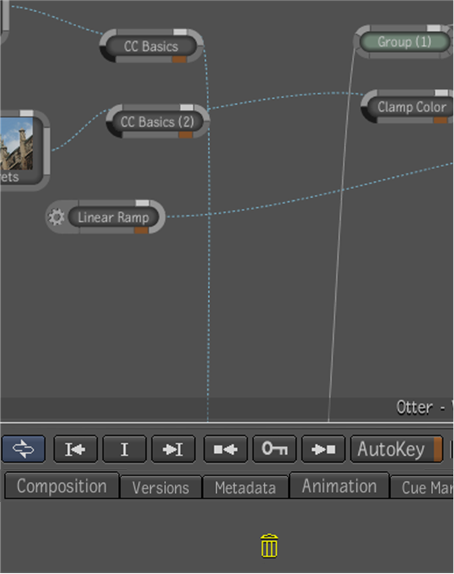
To delete one or more nodes:
- Select the node or nodes you want to delete.
- Then, do one of the following. Either right-click one of the nodes and select Delete, or press . Or drag a reasonable distance outside the bottom edge of the Schematic view and release. A garbage icon will appear to indicate
the point at which it is possible to release the node.
NoteYou can also delete nodes by selecting then and clicking the Delete button in the Tool Options area of the tool.
To select all nodes, do one of the following:
- Right-click the Schematic view and choose Select All.
- Press (for Windows and Linux) or (for Mac OS).
All nodes and connection lines are selected in the Schematic view.
 Except where otherwise noted, this work is licensed under a Creative Commons Attribution-NonCommercial-ShareAlike 3.0 Unported License