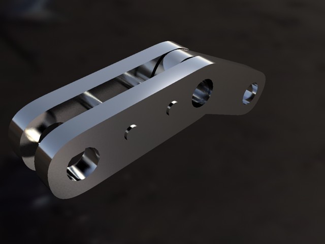
No round corners
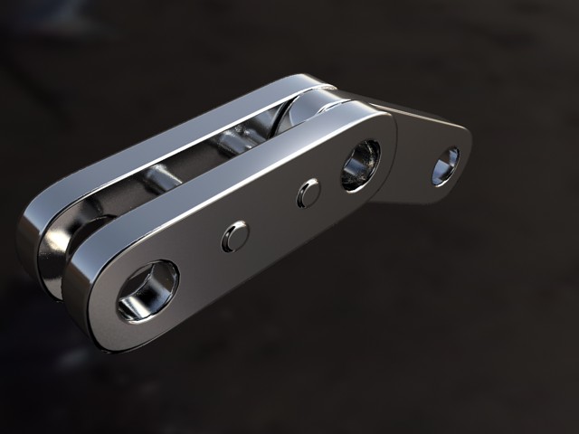
Round corners
CG has a tendency to look "unrealistic" because edges of objects are geometrically sharp, whereas all edges in the real world are slightly rounded, chamfered, worn or filleted in some manner. This rounded edge tends to "catch the light" and create highlights that make edges more visually appealing.
The mia_roundcorners shader can create an illusion of "rounded edges" at render time. This feature is primarily intended to speed up modeling, where things like a table top need not be created with actual filleted or chamfered edges.
The shader perturbs the normal vector, and should be applied where bump maps are normally used, e.g. in the bump parameter if the mia_material.
The function is not a displacement, it is merely a shading effect (like bump mapping) and is best suited for straight edges and simple geometry, not advanced highly curved geometry.
declare shader vector "mia_roundcorners" (
        scalar "radius",
        boolean "allow_different_materials",
        shader  "bump",
        integer "bump_mode",
        vector  "bump_vector",
    )
    version 3
    apply texture
end declare
The radius parameter defines the radius of the rounding effect, in world space units.
When allow_different_materials is off, the rounding effect happens only against faces with the same material. If it is on the rounding effect happens against any face of any material.
The bump parameter is a passthrough to any other bump shader that handles additional bumping of the surface, for example mib_bump_map2 or similar. This parameter is only used if bump_mode is 0.
To better support OEM integration, the new parameters bump_mode and bump_vector was introduced.
bump_mode defines the coordinate space of the bump_vector, as well as that of the return value of the shader itself (which is also a vector), and if it is interpreted as a "normal vector perturbation" or a whole new "normal vector"`.
The following values are legal:
The "add" modes mean that the vector contains a normal perturbation, i.e. a modification that is "added" to the current normal. The "set" mode means that the actual normal is replaced by the incoming vector, interpreted in the aforementioned coordinate space. Equally for output, an "add" mode implies that the shader returns a perturbation vector intended to be added to the current normal, and "set" mode implies that it returns a whole normal vector. In neither case does the shader actually modify the current normal by itself.
The mia_envblur shader works by accepting some other environment shader as input, which would usually be a shader that performs an environment lookup in an HDRI environment map. When the render starts, it performs a one-time setup and rasterizes the result of this environment shader in a special format into an internal pyramidal filter structure.
Then, when rendering proceeds, the shader can perform an extremely efficient blurring operation in this environment map in way that looks very similar to shooting an extremely large amount of glossy reflection rays into it; i.e. it yields a perfectly smooth result - quickly.
declare shader "mia_envblur" (
        shader  "environment",
        scalar  "blur"               default 0.0,
        boolean "mia_material_blur"  default on,
        integer "resolution"         default 200
    )
    version 1
    apply environment, texture
end declare
environment is the actual environment shader looked up by this shader. If this is not specified, the global camera environment is used.
blur is the amount of blur (range 0.0 to 1.0) applied on the image. If this is 0.0, the internal bitmap is bypassed and the environment shader is looked up directly, as if the mia_envblur shader was not there.
The blur amount can be automatically calculated setting mia_material_blur to on. Any reflective environment lookup performed by mia_material will cause the appropriate blur in mia_envblur. Leave blur at 0.0 in this case. This feature is described in more detail on page Automatic Blur.
resolution is the resolution of the internal pyramidal data structure used for the filtering. The default value of 200 means that a map of 200 x 200 samples are taken and stored, for subsequent filtering. This should be set high enough to resolve the smallest feature in the environment map. 200 is generally enough for any still image - animations need higher resolutions (1000).
It is important to remember that mia_envblur does a one time rasterization of the environment shader at start up time. This means that that shader must be constant across the scene, and cannot be a complicated position-dependent blend of environment shaders. The environment can still change over time, since the rasterization step is performed anew each frame.
The environment blur shader mia_envblur is intended to increase quality and performance of renderings that are largely reflecting the mental ray environment (i.e. that do not primarily reflect other objects).
The shader is primarily useful in product visualization renderings that are surrounded by an HDRI environment map for reflections, and also for visual effects work where one wants to help integrate CG objects in a real scene with the help of HDRI reflections, and want a smooth yet fast lookup.
The shader is not as useful for interior architectural renderings, since in those (enclosed) scenes, most reflection rays are bound to hit other objects; the purpose of this shader is to help reflection rays that do not hit other objects, i.e. the largest benefit is in an "open" scene 1.
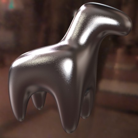
Here an example object is reflecting an environment map 2 with no glossiness (i.e. perfect mirror reflection). This looks fine, because there is no quasi-random sampling performed.
But what is we want to make a glossy reflection? If one simply uses the glossy reflection of mia_material one receives the following result:
It is obvious that the default 8 glossy reflection samples are nowhere near enough, especially with an environment map with such high contrasts in it. Trying with 100 glossy samples (at a large performance hit) the result is:
This is better, but still nowhere near a "smooth" glossy reflection. The 100 samples made the rendering an order of magnitude slower, and it is still not enough! What can we do?
What we want to is not look up the environment multiple times. Not 8 times, nor 100 times, but once, except we want that lookup to already contain the desired blur!
This is accomplished by enabling the single_env_sample parameter of mia_material and then apply mia_envblur as our environment shader and our "original" environment map as the environment parameter of mia_envblur.
Going back to our original 8 glossy samples, the following result can be rendered, very quickly:
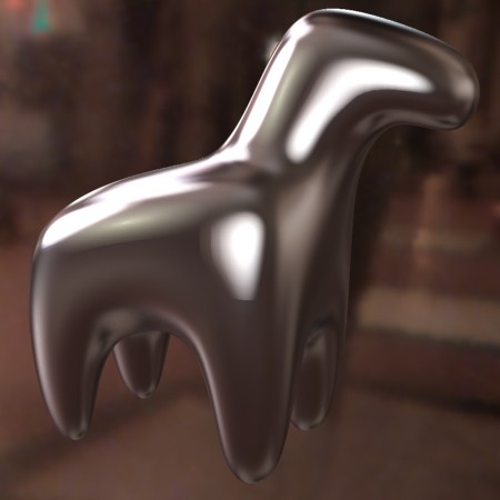
This looks much better, and renders much faster, but the level of blur is constant. A much more advanced way is to let mia_envblur derive the blur to apply by enabling mia_material_blur.
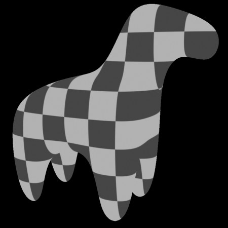
Assume we have applied the following map to the refl_gloss parameter of the mia_material:
The resulting render, with the help of mia_envblur will be this:
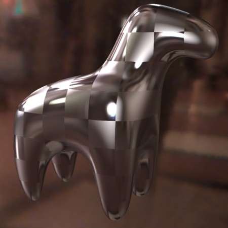
Please note that mia_envblur shader only supports isotropic lookups, and will ignore any anisotropy parameters of mia_material when using it like this.
Also, do not forget to use the single_env_sample feature; just blurring the environment map is often not enough to combat the noise.
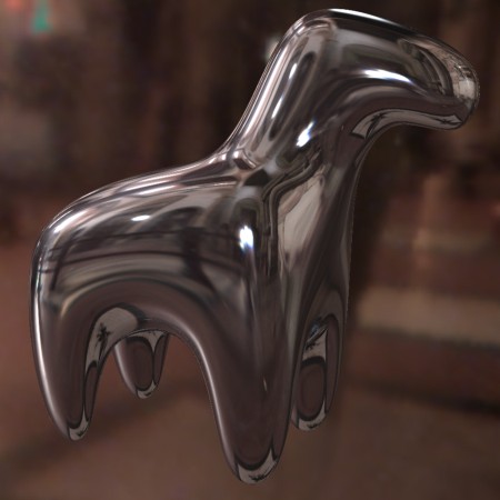
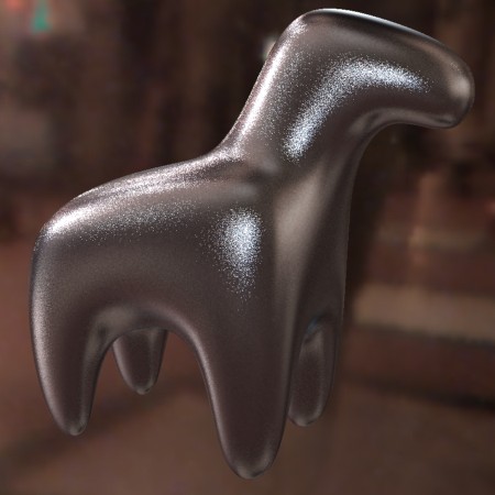
Keep in mind that other objects will still reflect in the traditional manner with multiple samples, and this feature only applies to environment lookups. Therefore it can be very advantageous to use refl_falloff_dist to limit "actual" reflections to nearby objects only, and let the environment take over for distant objects3:
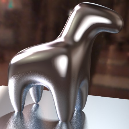
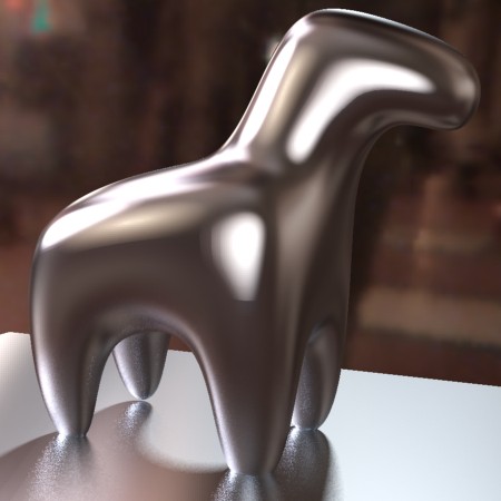
In the right image the legs of the horse only reflect very near to the floor, and conversely the horse only reflects the very nearest parts of the floor - the rest is environment reflections. This yields a faster result than actually tracing those reflections, and cuts down on the noise in the image.
The mia_light_surface shader is primarily intended to help creating physically plausible renders of the "visible" portion of a light source - the actual tube in a fluorescent tube, the actual bulb in a light bulb, etc. while still using a traditional CG "light" to create the illumination of the scene (see the use cases described below).
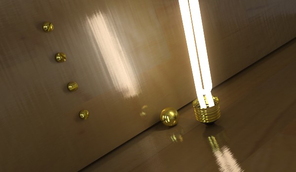
In the image above, actual illumination comes from a long thin rectangular area light, which is set not to cause any specular highlights. The visible "glow" of the fluorescent tube is set be visible in reflections (and hence become our much more accurate "highlight") but still be invisible to FG rays, so it will not be incorrectly picked up as additional light.
The mia_light_surface shader can either provide a color all by itself, or derive the color from an existing (set of) light(s) in the scene.
The shader itself only returns a color and does not do any other shading per se. A tip is to use it plugged into the additional_color of mia_material.
These are the parameters of the mia_light_surface shader:
declare shader "mia_light_surface" (
        color           "color"        default 1 1 1,
        scalar      "intensity"    default 1.0,
        scalar      "fg_contrib"   default 0.0,
        scalar      "refl_contrib" default 0.0,
        boolean     "use_lights",
        scalar      "lights_multiplier" default 1.0,
        vector      "lights_eval_point" default 0.0 0.0 0.0,
        array light "lights"
    )
    version 3
    apply texture
end declare
color is the overall color, and applies both to built in light or light derived from light sources.
intensity is the intensity of the "built in" light, i.e. the surface will appear to the camera to have an intensity of color multiplied by intensity (assuming use_lights is off - see below).
fg_contrib is how much of the light that is visible to FG rays, and refl_contrib how much that is visible to reflection rays.
When use_lights is on, the lights listed in the lights array are polled and their intensity (multiplied by the lights_multiplier) is added to the output dictated by the intensity parameter; i.e. if L is the output of all lights in the lights list, the final output color of the shader is:
color * (L * lights_multiplier + intensity)
When lights_eval_point is 0,0,0 the intensity of the light is evaluated (with shadows disabled) at the point in 3D space that is being shaded. Since this may vary in an undesirable way for a light that has an IES profile, one can specify an explicit point at which the light color is evaluated. This point is in the coordinate space of the light.
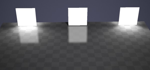
In the real world every light emitting object is visible, has an area, and emits light from that area. When using FG, mental ray will treat any surface that adds light energy into the scene as if it was a light source. However, to get the best possible quality out of this, one need very high FG settings, with long render times.
Light sources in computer graphics can be either point sources or area lights, and the area lights themselves may, or may not, be visible in the rendering. In most cases It is simply more efficient to use actual light sources:
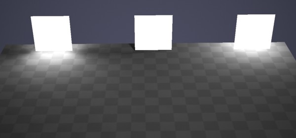
The image above shows 3 patches that are all using the mia_light_surface above a checkered plane. The leftmost patch has it's fg_contrib set to 1.0 (and is hence illuminating the floor), the other two has it set to 0.0. But the rightmost patch has a point light hidden behind it.
At close distances (or with very large light sources, like the entire outdoor sky) FG can illuminate objects just fine with very good quality. At long distances or with small sources, using an explicit light source is much more efficient.
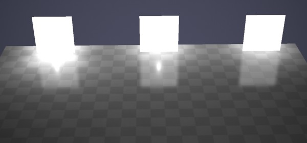
mia_light_surface gives separate control if the object should be "seen" by reflection rays or FG rays (and how much) via the fg_contrib and refl_contrib parameters. This image uses a slightly reflective checkered plane to illustrate this. No light sources are used behind these patches:
The leftmost patch is visible both to FG (illuminates the plane) and reflection (reflects in the floor). The center patch does not illuminate (fg_contrib is zero) and the rightmost does not reflect (refl_contrib is zero).
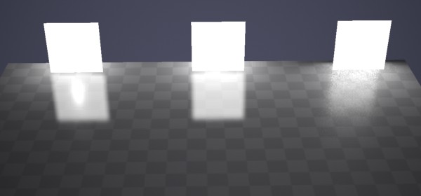
In the real world, the visible light emitting objects are both visible to any camera photographing the scene, as well as reflect (glossily) in other objects. In computer graphics, light sources tend to be invisible to the camera, and their reflections are "cheated" with the help of "highlights" by material shaders.
The mia_material supports a protocol for light sources to tell it if they should generate highlights or not. This is implemented by most OEM applications light sources, look for flags like "Affect Specular" or "Emit Specular" or similar on the lights.
There is a light hidden behind each of the patches in the image above. The leftmost is emitting both specular- and diffuse light. The middle one is only emitting specular light, and the rightmost is only emitting diffuse light. Furthermore, the rightmost patch has it's fg_contrib set to zero.
As we can see, the leftmost patch creates too much illumination, since we get illumination both from the light and from the patch. The center patch generates the strange effect of a small "highlight" (our light source is just a point light) inside the reflection of what we are trying to sell as "the visible light".
In this case this effect is distracting, so we want it disabled - like we have done on the light on the right. That is the way to go; let the surface handle the reflection, not the illumination, and let the light handle the illumination, not the reflection (i.e. no traditional "specular highlight").
An alternative, when using area lights, is to allow the area light to create the specular highlights:
This illustrates the alternative. The leftmost patch again uses a point light with specular on. This is what we do not want, since it looks strange. The other two patches use an area light. The middle patch has the area lights specularity turned off and the patch has refl_contrib set to 1.0, the right has the lights specular enabled, and a refl_contrib of zero.
As we can see, both variants on the right side "work", so it is a matter of choice which method is used for area lights.
However, the middle method tends to be preferred, because often one is using a geometrically simple area light (sphere, rectangle, etc.) in place of an object that is actually geometrically complex (a neon sign, for example). In those cases one definitely want to use the method in which the object is reflected, and the light does not emit specular light:
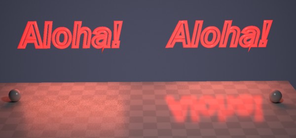
Both neon signs use a rectangular area light for their illumination, and both cast nice area shadows (as witnessed by the small spheres). But the sign on the left has a blatantly rectangular "reflection", which does not make any sense. For this use, definitely use the method on the right side, with the lights specularity off, and the surface's refl_contrib nonzero.
In a real world luminaire, complex interactions between the bulb, the reflector, and various occluders determine the final distribution of light flying off into the scene.
Naturally, one do not want to consider all those minute details just to make a rendering of a desk lamp, and indeed, the problem comes pre-solved in the form of measured data (i.e. IES or EULUMDAT files).
The mia_light_surface shader can get its intensity from a light. This saves the user the time of keeping the intensity and color of the "visible surface" in sync with the intensity and color of the light source. If the use_lights is on and some light is passed in the lights parameter, this happens automatically.
This works fine for isotropic point lights and similar, but when using measured light data, one can run into an issue:
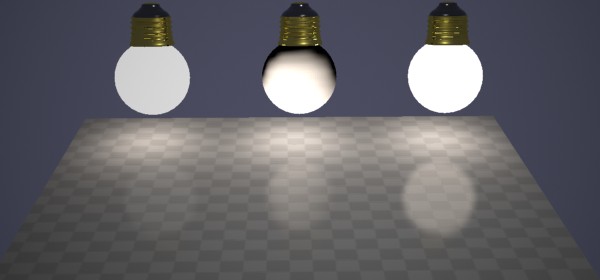
The above scene contains three spheres. Lets assume they are the models of the light bulbs of some desk lamp. They each contain a light that has an IES profile fitting that luminaire applied.
The leftmost sphere uses mia_light_surface with a manual setting, i.e. use_lights is off. The user is responsible for making sure the intensity and color of the surface is "correct", as well as manually keeping it in sync with any animated intensity changes etc.
The center sphere uses use_lights, but we get a very strange effect from it; half our lightbulb is dark. This is because the IES profile we chose only emits light in the down direction. Since the light source is in the center of the sphere, only the lower half of the sphere will gather any intensity values off the light!
Clearly this is not desirable; the IES profile is a compound effect applying to the entire luminaire, and should not be "painted" onto the light bulb itself!
The solution is to use lights_eval_point as is done on the rightmost sphere. Here a point just in front of the light is picked (in the lights own coordinate space) as the "evaluation point". Each point on the sphere (regardless of its location) will have the intensity "measured" at that point in space.
This gives the sphere a color that automatically follows any intensity- and color-changes of the light, yet is uniform across the surface of the sphere. This sphere will reflect correctly in a more plausible way than a traditional "highlight" would.
In conclusion: The mia_light_surface shader
allows...