Basic data structures are used to contain the components that represent the polygon (faces, edges, vertices). These structures are then further encapsulated in polygonal shape nodes to provide structure within the core of the Maya architecture—the dependency graph. Each of these concepts is crucial for manipulating and interfacing with polygons in Maya.
Polygonal meshes are composed of three basic components:
Beyond the three basic polygon components there are two additional components, which are just as important in understanding how to work with polygons in Maya:
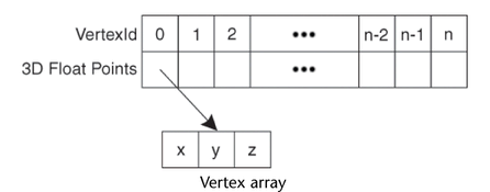
The vertices of a polygonal mesh are stored in a simple array of 3D float points, each point having a vertex id based on the given index in the array. Both edges and faces are based on this array.
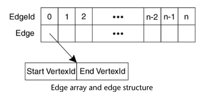
The edges of a polygonal mesh are stored in an edge array. Each edge in the edge array consists of two integers that make up each vertex id. The first integer represents the start vertex of the edge while the second integer represents the end vertex of the edge. This provides edges with vertex composition, direction, and an edge id (represented by the indices of the edge array).
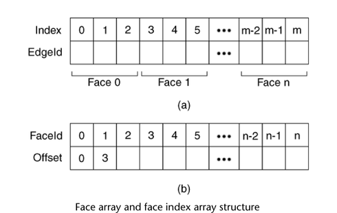
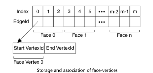
The faces of a polygonal mesh are stored in an integer array. Each face is described by a number of sequences of integers—each integer representing an edge id. The first sequence of edges represents the boundary of the face. Any subsequent sequences represent holes in the face. Internal flags mark the start and end of each sequence as well as the end of the face description are marked by internal flags.
A face offset or index array compliments the face array. This array holds the starting positions of each face description in the face array. Since each face can be composed of a series of a number of edges as well as multiple sequences, it can be redundant to traverse the array looking for the beginning of each face. This face index array provides a quick access to information about each face. The index of each face position is referred to as the face id of the given face. In addition to the elements marking the start of each face, an element is appended to the end of the face index array to mark the final index in the face list. This final index figure lets you quickly access the order of each face (number of edges/vertices in the face).
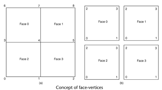
In cases where faces are adjacent to each other, the faces share common vertices. You often need to associate data to a specific vertex of a specific face, while distinguishing that specific vertex from any faces that share it. These are known as face-vertices.
Face-vertices are conceptual components used by polygonal features such as color per vertex and UVs. Face-vertices are represented by an existing data structure—the face array and face index array. Each face vertex is associated with a given face id and vertex id. You can use the face id to find the offset into the face array and subsequently search for the given vertex id in the edge loops by using the start vertices of each edge. Notice that each vertex id in each face is a unique index for the given vertex of a face—a face-vertex index. A shared vertex id appears multiple times across the face array, appearing once in each face description that shares the vertex.
In the following illustration, (a) depicts the topology of a four face polygonal plane while (b) shows the face-vertex view of that four face polygonal plane. In the face-vertex view, each face is separated, holding its own individual vertices. Each individual vertex is labeled using a vertex index local to each face (that is, 0 to 3). Each face-vertex is associated with a UV. However this does not guarantee a unique UV per face-vertex. By default, for face-vertices that represent a shared vertex, such as vertex 4 in (a), each face-vertex is associated with the same UV, thus sharing a UV. “Splitting” a UV provides each face vertex of a shared vertex a unique UV.
The following figure illustrates how the view of the face array can be changed to interpret it as a representation of face-vertices.
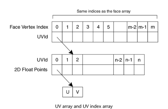
UVs rely heavily on the concept of face-vertices. UVs correspond to a 2D plane used to map a texture onto a polygonal surface. Texture mapping is done on a face- by-face basis. As a result, UVs are mapped on a face-vertex basis to allow each face its own set of map coordinates, if desired. The structure that holds UVs in Maya consists of two arrays:
The first array associates each face vertex with a given UVId or none at all if the face that the face-vertex belongs to is not mapped. Each UVId then corresponds to an index in the UV list that holds the 2D point (U and V float values) where the UV is situated on the UV space.
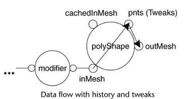
Alone, the components are capable of representing the geometry of a mesh. However to coincide with the flexibility of the Maya architecture, these structures are integrated into the dependency graph architecture in the form of a polygonal shape node. The polygonal shape node holds four fundamental attributes: an inMesh, an outMesh, a cachedInMesh, and pnts (tweaks), as shown in the following illustration.
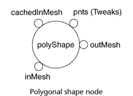
The four basic attributes of the polyShape node are explained below. Each of the first three attributes cache their own copy of the mesh for the polyShape node. The differences between each represent the different stage of evaluation during a DG evaluation.
The standard input attribute of the polyShape node. This attribute accepts input mesh data from other DG nodes and forwards the data through the node to the outMesh. It stores its own internal copy of the geometry being passed into the node. inMesh is only valid if there is an input connection. Otherwise it is ignored.
The standard output attribute of the polyShape node. This attribute receives input mesh data from either the inMesh or cachedInMesh (depending on the node state) and stores it as its own internal copy of the mesh. The outMesh geometry represents the final geometry of the shape and is always valid.
The simulated input attribute of the polyShape node. This attribute is only ever initialized and used in the case where the inMesh attribute is invalid (that is, no input connection) and tweaks exist on the mesh. It also stores its own internal copy of the geometry.
The tweaks attribute. This is an array attribute that stores the position offsets for each vertex in the geometry, representing manual “tweaks” or modifications to these basic components. The presence of tweaks is determined by looking for a non-zero value in the array attribute.
The data flow of the polyShape node is dependent on two factors:
A node with construction history and tweaks implies that there is an input connection present on the node and a non-zero value present in the pnts attribute. In this case the inMesh is valid and upon receiving the mesh data from the upstream history, the pnts attribute is applied to the inMesh data and the resultant mesh stored in the outMesh.
For a node with construction history and no tweaks, the inMesh is redirected to the outMesh. The following illustration shows the data flow for the case where construction history is present as well as tweaks.
A node without construction history and without tweaks implies that there is no input connection present on the node and an all-zero pnts attribute array. In this case the inMesh is invalid. However since there is no need to redirect any data, nor apply any tweaks, the geometry of the polyShape node is the outMesh itself.
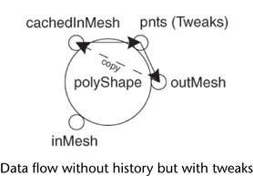
A node without construction history and with tweaks implies that there is no input connection present on the node and a non-zero value present in the pnts attribute. In this case you cannot use the outMesh since you need to apply tweaks. Applying tweaks directly on the outMesh will result in losing the former values without the ability to undo. As a result, you need a simulated input—the cachedInMesh—which will store the current state of the outMesh before tweaks are applied and re-evaluate the node. The outMesh geometry is copied to cachedInMesh as soon as tweaks are applied to the node. From there the cachedInMesh behaves just like the inMesh with construction history and tweaks. The pnts attribute is applied to the cachedInMesh and subsequently forwarded to the outMesh.
Interfacing with a polyShape node involves two basic actions:
Most of the Poly API provides accessor and mutator methods that understand the anatomy of a polyShape node. As a result, you can use these methods to properly interface with the geometry of the polyShape node. However, you may need to interface with the node directly, for example, when backing up the mesh data of a node. These operations involve mostly DG operations such as retrieving plugs, setting plugs and retrieving plug data, etc.
The outMesh always has the most up to date information as it represents the final resultant mesh in the polyShape node. Consequently, the outMesh is where all accessors retrieve their information. In the example of backing up a mesh, it is the outMesh that you would backup as it represents the current state of the node.
The same two factors that affect the data flow of the node also affect how the node should be modified—construction history and tweaks.
In the case where construction history is present (an input connection exists), there is an upstream node from the polyShape node. During a DG evaluation the data that is passed to the polyShape node will overwrite the inMesh of the polyShape node, which in turn updates the outMesh. As a result, setting an attribute on the polyShape node or any other “direct modification” to the node should be avoided if history exists, as the change will be overwritten by the next DG evaluation. To modify the mesh, a modifier node containing the modification needs to be inserted ahead of the polyShape node. This applies regardless of the presence of tweaks, so long as history exists. For more details see Construction History. This case requires less direct interaction with the node itself since the DG requires that a modifier node be inserted ahead to avoid overwriting the changes made.
In the case where construction history is not present, you can create history or modify the node directly. This depends on the “Record History” preference in Maya. If the user chooses to create history, then the case is similar to the above case with some minor tweaks and involves little interaction with the node itself other than setting up connections.
Attempting to write to the node directly where you do not want to create history involves more interaction and understanding of the purpose of the shape’s attribute composition. For a node without history and tweaks, the outMesh represents the only geometry of the shape node with all other mesh attributes ignored. Under such a case you can operate directly on the outMesh. So if you obtain a backup mesh, you can reapply the backup mesh to the outMesh and the node will be reverted to its original state.
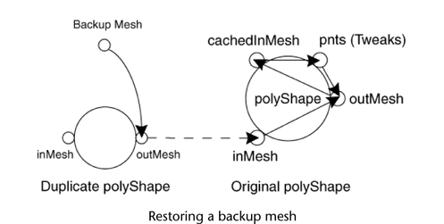
When the node is without history but has tweaks, a cachedInMesh is generated as a copy of the outMesh and used to apply the tweaks to obtain the final mesh. During the outMesh copy to the cachedInMesh the node performs some synchronization among its attributes which is internal to the node and inaccessible from the API. This means you need to update the outMesh before the cachedInMesh is initialized. (In the example of backing up a mesh, you risk destabilizing the node if you simply copy the backup mesh to the cachedInMesh.) The recommended approach is to do the following:
(You could use the polyDuplicateAndConnect MEL command to perform the first three steps.)
This updates the outMesh, through the inMesh so that once the inMesh is invalidated by the disconnected node, the cachedInMesh will hold the original mesh backup before it applies the tweaks. This is shown in the polyModifierCmd example. The following illustration describes the data flow used to restore the backup of a mesh.