Converts the selected NURBS objects to polygons.
Modify > Convert
> NURBS to Polygons > 
Attaching multiple output meshes
Produces a single mesh, even if the original NURBS object consists of separate surfaces.
For example, if you convert a NURBS cube (which consists of six separate faces) with Attach Multiple Output Meshes on, the resulting polygon cube will consist of a single mesh. If Attach Multiple Output Meshes is off, the polygon cube will consist of six separate meshes.
When Match Render Tessellation is turned on it uses the existing render tessellation values that are set for the NURBS surface when converting it to a polygon mesh. As a result, the converted polygon mesh will match the rendered version of the NURBS surface. When History is turned on the NURBS to Polygon conversion will update whenever the NURBS render tessellation values are modified.
Choosing a tessellation method
Tessellation means that you create a set of polygons from NURBS geometry. Each tessellation method provides you with options that let you control the resulting polygonal surface.
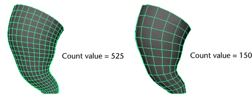
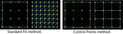
There are four tessellation methods: “Standard fit”, “General”, “Count”, and “Control Points”.
Standard Fit is the default tessellation method. It is “adaptive” tessellation, meaning that the following options are used to determine when to stop the tessellation.
For example, the tessellation stops at the Fractional Tolerance value you set. If there is an edge shorter than the Minimal Edge Length, the tessellation stops on that edge. If the surface is flat enough within the edge (the specified chord/height ratio is small enough), the tessellation stops there.
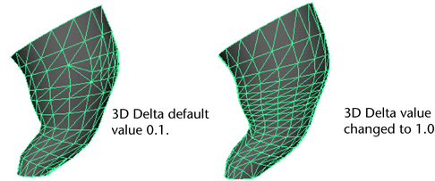
The Chord Height Ratio is the ratio between the maximum distance of the curve from the polygon edge used to approximate it and the chord length. The chord length is the linear distance between two polygon vertices.
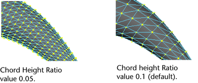
Valid values range between 0 and 1, where larger values result in fewer polygon vertices.
For example, the default value, 0.1, means that the height must be larger than 1/10 of the chord length before additional edit points are created.
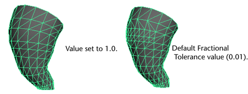
The Fractional Tolerance value determines the degree of accuracy maintained between the original surface and the interpolated polygonal surfaces. The default is to be accurate to within 0.01 units, where a unit refers to the current unit of linear measure (the default unit of measure is centimeters). Therefore, at no point will the polygonal surface be more than the tolerance distance away from the original NURBS surface.
In this next example, notice how you can enhance the polygonal surface’s accuracy when you change the Fractional Tolerance value from 1 to 0.01.
Setting the initial tessellation controls
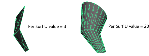
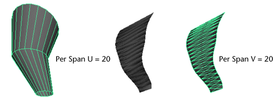
Unless Use Chord Height or Use Chord Height Ratio is turned on, a uniform tessellation is performed. Each span/surface is split into a number of polygons depending on the Number U and V values you set.
Specifying the secondary tessellation controls
If Use Chord Height or Use Chord Height Ratio is turned on, you can set a specific value for both the Chord Height and the Chord Height Ratio. A value greater than 0 results in fewer polygon vertices if the ratio on the curve is greater than the current value. For example, the default value, 0.1, means that the height must be larger than 1/10 of the chord length before additional edit points are created.
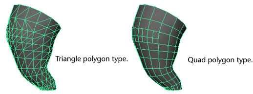
Turn Edge Swap on to produce triangles with the opposite orientation for the final quadrilateral.
When you use the Control Points Tessellation Method:
When you use the Attach Multiple Output Meshes option, the operation may fail to attach surfaces for a variety of reasons: