Component
selection and transformation is one fundamental method for editing
the shape of a polygon mesh. As you model, you’ll find yourself
frequently examining and then refining the position of the polygon
components (vertices, edges, and faces) while working in the various
scene views so they match the reference images on the image planes.
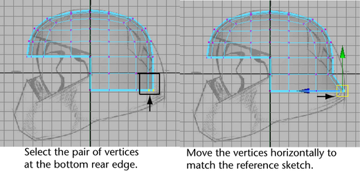
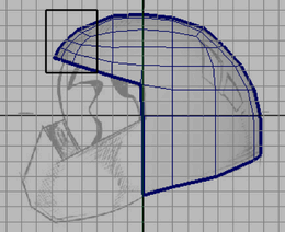
To manually reposition the vertices on
the rear of the helmet
- Right-click
the helmet and select Vertex from
the marking menu that appears.
- In the side view, select the pair of
vertices at the rear lower edge (see image) by dragging a bounding
box around them.
- In the Toolbox,
click the Move Tool.
- In the side view, click-drag the blue
arrow on the Move Tool manipulator towards
the right until the vertices are repositioned so that your helmet matches
the reference sketch on the image plane.
By moving the vertex
as well as the vertex adjacent to it along the axis of symmetry,
you ensure that the symmetrical shape of the helmet is maintained.
If you move one vertex independently of the other it may result
in an unwanted bump or valley in the mesh. These types of anomalies
will become more apparent when you copy the completed half of the
mesh across the axis of symmetry.
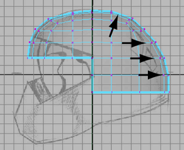
- Repeat steps 2 through 4 for the other
pairs of vertices on the rear of the helmet. Ensure that the edge
loops appear smooth in relation to each other.
When you have finished,
the back region of the helmet should closely match the reference
image on your image plane.
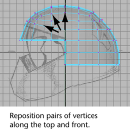
- In the side view, select other pairs
of vertices along the top and front of the helmet and move them
in a similar fashion so they match the reference image. Do not reposition
the vertices for the top of the face shield yet.
TipYou can click in
the center of the Move Tool manipulator to drag
a vertex selection freely.
Next, you’ll reposition
the border edges that lie along the bottom edge of the mesh. You
can select these edge types using the Select Border Edge Tool.
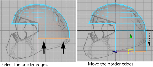
To reposition the lower border edges
on the helmet
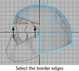
- In the side view, select the lowest horizontal
edge loop on the helmet by choosing
Select > Select Border Edge Tool from
the main menu, and then clicking the first and then the last edge
on the loop as indicated in the image below.
- Using the Move Tool,
drag the selected edge loop downwards until the left hand vertex
roughly matches the lower edge indicated in the reference sketch.
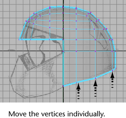
- In the side view, select and reposition
the remaining vertices individually on the edge loop using the Move
Tool so they match the reference sketch.
NoteUp to this point
in the lesson, you’ve been instructed to reposition the vertices
on the helmet mesh only within the side view (Y, Z plane). Once
you achieve the shape you want in the side view you will then concentrate
on how the model appears when viewed from the front and perspective
views.
To edit the border edges on the upper
edge of the face shield
- From
the Select menu, choose Select
Border Edge Tool.
- In the side view, click the first border
edge that will be used as the upper edge of the face shield, then
click the last border edge (see image).
The border edges in between
are selected.
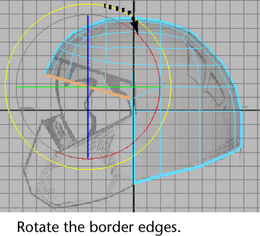
- In
the Toolbox, select the Rotate
Tool by clicking its icon.
- In the side view, click-drag the rotate
manipulator in a clockwise direction until the border edges are
rotated at roughly the same angle as the corresponding edge in the
reference sketch.
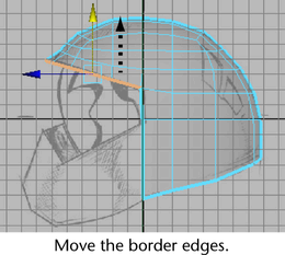
- With the border edges still selected,
click the Move Tool again and drag the
green manipulator upwards to match the location of the border edges in
the reference sketch.
- Reposition the pairs of vertices on the
upper front of the helmet to match the reference sketch.
At this point in the
lesson, the outline of your helmet should roughly match the helmet
in the side view reference image. If it doesn’t, review the earlier steps
in this lesson and make any adjustments to your polygonal mesh as required.
If you view your helmet
in the front orthographic view, you’ll notice that the helmet shows
a wider profile from this view than the reference sketch. In the next
steps you’ll correct this using the front and top orthographic views
of the helmet for reference.
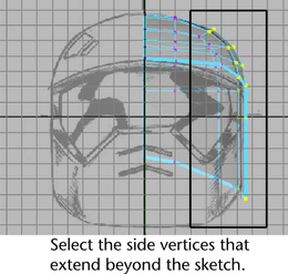
To reposition vertices on the side of
the helmet to match the sketch
- Display the front view.
- In the front view, select the vertices
that extend beyond the outline of the helmet as shown in the reference
sketch (see image).
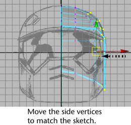
- In the front view, move these vertices
to the left until they match the widest area of the helmet in the
reference sketch (see image).
When you view your helmet
from the top orthographic view the region between the side and rear
of the helmet appears a bit flat in relation to the other areas.
To correct this you can move the other vertices in this region outwards
in a similar fashion so the curvature in this area appears fuller
and more rounded. However, viewing only from the orthographic views
can be limiting, and you should also use the perspective view to
examine the mesh.
To examine the mesh using the perspective
view
- Enlarge the perspective view.
- Dolly and tumble the perspective view
while you closely examine the helmet mesh.
As you examine the vertices
along any particular edge loop, the vertices on the mesh should
appear to cascade in a smooth gradual fashion to create the curvature
of the mesh with no undesirable spikes or dips.
Ensuring that the mesh
appears relatively smooth at various stages throughout the modeling
process will reduce the possibility for issues when you create a
high resolution version of the mesh later on.
If you find areas where
one vertex (or more) appears to protrude outwards (or recedes) on
the mesh in relation to neighboring vertices, you can correct these
protruding regions by repositioning the affected vertices in the
perspective view.