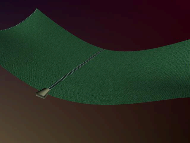
This example will show
you how to create a zipper for your nCloth.
Set up the zipper
In order to create a
zipper, you will first create a pair of nCloth objects for the zipper
to connect.
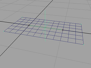
To create the Input Mesh for your cloth
- Select
Create > Polygon Primitives > Plane >
 .
.
The Polygon
Plane Options window opens.
- Select Edit > Reset Settings.
- Set the Plane options
as follows:
- Width divisions:
6
- Height divisions:
6
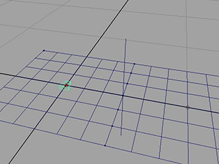
- Click Create.
Maya creates a plane
centered at the origin.
- Select
Create > Polygon Primitives > Plane.
A second plane identical
to the first plane is created in the same position.
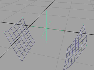
To place the planes side by side
- Select the second plane.
- Open the Channel Box.
- Set TranslateX to
1.
The second plane moves
to the right such that the edges of the two planes touch.
To make the planes nCloth
- Click the first plane and
 -click
the other to select both.
-click
the other to select both.
- Select
nMesh > Create nCloth.
Maya makes the planes
nCloth.
- Playback the simulation.
The planes fall.
To prevent the cloth
from uniformly falling, you need to constrain its corners.
To constrain the corners of the cloth
- -select
both nCloth planes.
-
 -click
the nCloth and select Vertex from
the marking menu to switch to Vertex mode.
-click
the nCloth and select Vertex from
the marking menu to switch to Vertex mode.
The planes’ vertices
appear.
- Select the vertices on the outer corners
of each plane for a total of four selected vertices.
- Select
nConstraint > Transform.
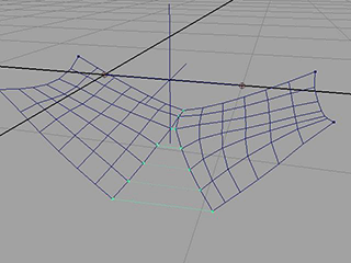
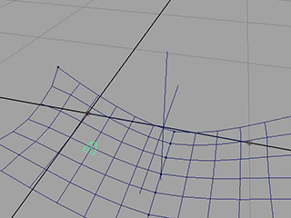
- Playback the nCloth simulation.
The pair of nCloths are
now held in place by their corners. Both cloths fall at the point
where they join.
To join the two nCloths at their center
- Select both nCloths.
- Switch to Vertex mode.
The nCloth vertices appear.
- Select all the vertices for both nCloths
along their intersection.
NoteSince the edges of
both nCloths are on top of each other you may have difficulty choosing
all the vertices on both planes. To make this process a bit easier,
you can move the planes slightly apart from each other and then select
the vertices. If you do this, make sure to return the planes to
their original position before continuing with this example.
- Select
nConstraint > Component to Component.
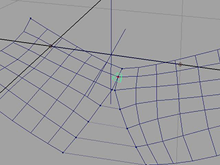
- Playback the nCloth simulation.
The two nCloth objects
are now joined at their center.
- Open the Attribute Editor and
select the DynamicConstraintShape tab.
- Set the Constraint Method to Weld.
The Weld setting
ensures that there is no space between the two nCloth objects.
Control the zipper's state
To control the state
of the zipper, you need to add a ramp texture to the Strength
Map Attribute. This allows you to control the strength
of the component to component bond between the two nCloth objects.
To add a ramp texture
- Select the first nCloth.
- Select
Window > Hypergraph: Connections.
Maya displays the Hypergraph:
Connections window.
- Select the nComponent3 node.
- Open the Attribute Editor and
click the small checkered box next to the Strength Map field.
The Create
Render Node window appears.
- In the right panel of the Create
Render Node window, click
 .
.
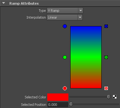
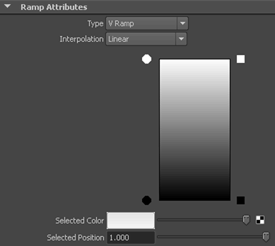
- In the Ramp Attributes section
of the Attribute Editor click the
box with an x at the center of the color ramp to delete the green
marker.
- Select the small red circle at the bottom
left of the color ramp. The colored box next to Selected
Color should change.
- Click the colored box next to Selected
Color
The Color
Chooser that appears.
- Select black and move
your mouse off the Color Chooser to close it.
The bottom of the color
ramp changes to black.
- In the Ramp Attributes section
of the Attribute Editor select the
small blue circle at the top left of the color ramp. The colored
box next to Selected Color should change.
- Click the colored box next to Selected
Color
The Color
Chooser appears.
- Select white and move
your mouse off the Color Chooser to close it.
The top of the color
ramp changes to white.
- Playback the simulation.
When you adjust the Selected
Color slide bar during playback, the two planes zip and
unzip.
Although adjusting the Selected
Color produces the desired result, it is not the only
possible method for controlling an nCloth zipper. You can use Texture
Placement to achieve the same effect with a greater degree
of control.
To edit the Texture Placement
- In the Ramp Attributes section
of the Attribute Editor select the
small circle at the bottom left of the color ramp.
- Set Selected Position to
0.45.
- Select the small circle at the top left
of the color ramp.
- Set Selected Position to
0.5.
- Select the place2dTexture1 tab.
- Set Repeat UV to
1.0, 0.25.
- Playback the simulation.
You can use the second
value of the Offset attribute to adjust
the state of the zipper during playback. A value of 0.55 produces
a fully zipped state whereas a value of 0.175 produces a fully unzipped
state.
You can now animate the
zipper by keyframing the Offset value.
Create the zipper object
To control the zipper,
you will need to create a zipper model and a hair follicle.
To create a controlling follicle
- Select the first plane.
- In the Dynamics menu
set select
Hair > Create Hair > .
The Create
Hair Options window appears.
- Select Edit > Reset Settings.
- Set the hair options as follows:
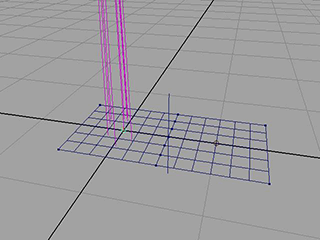
- Click Create Hairs.
A single hair follicle
with a number of hairs appears. For this example you will only make
use of the follicle, not the actual hair.
- Select
Window > Outliner.
The Outliner window
appears.
- Select hairSystem1 and pfxHair1 and press
 .
.
- Select hairSystem1Follicles and then
pPlane1Follicle.
- Select curve1 and press .
You now have a single
follicle that you can use to control the zipper. You now need a
model to represent the zipper.
To create a zipper model
- Select
Create > Polygon Primitives > Cube > .
The Polygon
Cube Options window appears.
- Select Edit > Reset Settings.
- Click Create.
- Open the Attribute Editor.
- Select the pCube1 tab and set the Scale
attribute to 0.092, 0.026, 0.094.
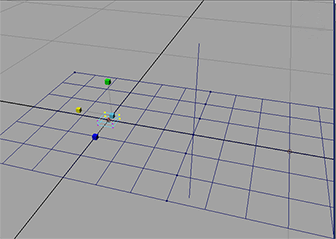
- Set the scene view to Vertex mode.
- Select the four vertices on the far side
of the cube and select the scale tool.
- Slowly drag the ScaleX handle to the
left until the cube forms a rough wedge shape. By dragging the ScaleX
handle, you ensure that the end of the cube is only resized in the
X direction.
- Select
Window > Outliner.
The Outliner window
appears.
- Select zipper in the Outliner and
middle drag it onto pPlane1Follicle5050.
- The zipper object is now attached to
the hair follicle you created earlier.
- Playback the simulation
The zipper now sticks
to the cloth.
Creating an expression
for a zipper
In order for the zipper
to behave properly it needs to be associated with the Offset V attribute
that controls the state of the two nCloth objects. To do this you
need to assign an expression that will drive the zipper’s interaction.
To position the zipper
- Select pPlane1FollicleShape5050.
- In the Attribute Editor set Parameter
U to 1.0.
The zipper should now
be aligned with the center of the cloth. Adjusting the Parameter
V attribute from 0 to 1.0 should now also move the zipper up
and down the length of the edge.
To create an expression
- Select
Window
> Animation Editors > Expression Editor.
The Expression
Editor window appears.
- Enter the following into the Expression field.
place2dTexture1.offsetV
= (1-pPlane1FollicleShape5050.parameterV) * 0.25 + 0.25
- Click Create and then Close.
Your zipper is now finished.
To open and close the zipper you can now adjust the Parameter
V attribute of the pPlane1Follicle5050.