Show in Contents

Add to Favorites

Home: Autodesk Maya Online Help

Constraining an IK system

Lesson 5: Inverse kinematics

Simplifying the display of a hierarchy

Limiting the range of motion of an IK system
It’s
possible to move ArmControl so that the mechanical arm fully extends to
a straight position or orients itself to other positions that you
don’t necessarily want.
You can limit the range of motion of the arm
to ensure that the IK system poses in a predictable manner. In the
following section, you limit the motion for the IK system as follows:
- Lock
the translation of the control object (ArmControl) so that it can
only move in Y and Z. By locking the X channel so it cannot be selected
or modified, the arm will not be able to move from side to side.
- Lock
the rotations on the swiveling base for the arm so it only rotates about
its Y axis, and not about its X or Z axes.
- Limit
the translations for the Arm Control so the mechanical arm cannot fully
extend to a straightened position.
To
lock the Translate X channel for ArmControl
- In
the Hypergraph, select the ArmControl
node.
- Open
the Channel Box to view the transform
channels for ArmControl.
- Set
all Translate or Rotate channels
to 0, if they are not already.
- In
the Channel Box, select the Translate
X channel by clicking on its name.
- Right
click on the word Translate X.
A drop-down menu appears.
- From
the drop-down menu, choose Lock Selected.
The numerical field for Translate
X is dimmed indicating that the channel is locked. If
you try to move ArmControl in X, it will not be possible unless you
unlock the Translate X channel.
To
lock the Rotate X and Z channels for
SwivelBase
- In
the Hypergraph, select only the
SwivelBase node.
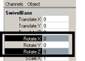
- Open
the Channel Box to view the rotation
channels for SwivelBase.
- Set
all Translate or Rotate channels
to 0, if they are not already.
- In
the Channel Box, select the Rotate
X and Rotate Z channels by control-clicking
on their names.
- Right
click on either of the selected names.
A drop-down menu appears.
- From
the drop-down menu, select Lock Selected.
To
confirm that the Rotate X & Z channels are
locked
- In
the Hypergraph, ensure only the
SwivelBase node is selected.
- In
the view, select Panels > Orthographic > top.
- In
the view, select Shading > Smooth Shade All.
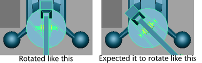
- Dolly
the top view so you can fully view the mechanical arm as shown below.
- Using
the ChannelBox, rotate SwivelBase
by typing 45 in the Rotate Y channel and pressing
Enter.
SwivelBase rotates in the view but the mechanical
arm does not rotate. You first might think something is wrong because
SwivelBase and all of the arm’s skeletons and surfaces are parented
into the same hierarchy.
NoteYou may sometimes discover that something
doesn’t work in the manner you originally anticipated when setting
up an IK system. When this occurs, it’s useful to stop and diagnose
why something is working the way it is (or not working the way it
should). In that way you can retrace your actions to determine where
the problem resides.
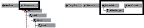
ArmControl and IK Handle are
not parented into the SwivelBase hierarchy. Because ArmControl and IK
Handle control the movements of the mechanical arm, they
must be parented into the SwivelBase hierarchy in order for the arm
to rotate when SwivelBase is rotated.
To parent the IK
Handle into the skeleton hierarchy
- In
the Hypergraph, select the SwivelBase
node.
- In
the ChannelBox, reset the Rotate
Y channel for SwivelBase to 0.
Setting any previous transformations to zero
is necessary before parenting the IK Handle beneath
SwivelBase in the hierarchy.
- Unselect
the SwivelBase node before performing the following steps.
- In
the Hypergraph menu, select View
> Frame All.
The Hypergraph displays
all the nodes for the scene.
- In
the Hypergraph, shift-select the
nodes named ikHandle1, ArmControl, and SwivelBase.
The order of selection is important. You want
to shift-select the items that will be the child nodes first, and
then shift-select the item that will be the parent node last.
- In
the main menu, select
Edit > Parent (Hotkey
p).
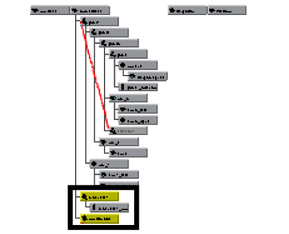
In the Hypergraph, IKHandle and
ArmControl are now child nodes for the SwivelBase node in the skeleton
hierarchy.
- In
the Hypergraph, select only SwivelBase.
- Using
the ChannelBox, set Rotate
Y for SwivelBase to 45.
When SwivelBase is rotated, the mechanical arm
rotates because of its relationship within the hierarchy.
- Reset
the Rotate Y value for SwivelBase
back to 0.
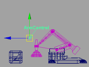
Finally, you want to limit how far Arm Control
can translate away from the base of the model so the arm does not
extend to a fully straightened position.
To determine the settings for the translation
limits you need to examine the position of the mechanical arm in
various positions while simultaneously viewing the translation values
in the ChannelBox.
To
determine translation limits for the Arm Control
- In
the Hypergraph, select ArmControl.
- Ensure
the Channel Box is open so you
can view the translate channels for ArmControl.
- In
the view, select Panels > Orthographic > side.
- Dolly
the side view so you can fully view the mechanical arm.
- Select
the Move Tool.
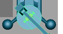
- In
the side view, press the middle mouse button and drag the mouse
diagonally until the mechanical arm is fully extended as shown below.
- In
the Channel Box, observe the number
that displays in the Translate Y and Z channels.
When the arm is diagonally articulated above
the cargo box, it is almost fully extended when the translation
values are roughly as follows:
- Translate
Y: 7.5
- Translate
Z: 1
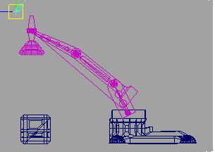
- In
the side view, press the middle mouse button and drag the mouse
in a diagonally until the mechanical arm is almost fully compressed
as shown below.
- In
the Channel Box, observe the numbers
that display in the Translate Y and Z channels.
When the arm is articulated to a compressed
pose, the translation values are roughly as follows:
- Translate
Y: -13
- Translate
Z: -13
These minimum and maximum values will be used
in the steps that follow as the minimum and maximum translation
limits for the ArmControl.
To
set translation limits for the Arm Control
- In
the Hypergraph, select the ArmControl
node.
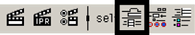
- Open
the Attribute Editor (
Window
> Attribute Editor or click on the Show/Hide
Attribute Editor icon on the Status Line).
The Attribute Editor displays
the nodes associated with Arm Control.
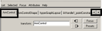
- In
the Attribute Editor, click the
ArmControl tab.
If the ArmControl tab is not visible, use the
left and right scrolls arrows to scroll the view sideways to view
it.
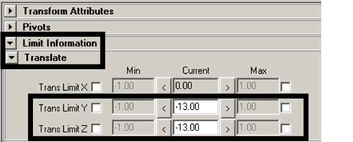
- In
the Attribute Editor, expand the Limit
Information attributes, and then the Translate attributes.
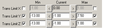
- In
the Translate attributes, click
the Trans Limit Y and Z check boxes
to undim the numerical boxes and then set the following values:
- Trans
Limit Y (Min): -13
- Trans
Limit Y (Max): 7.5
- Trans
Limit Z (Min): -13
- Trans
Limit Z (Max): 1
- Hide
the Attribute Editor.
- Select
ArmControl.
- In
the side view, move ArmControl to test the range of movement for
the IK system.
The mechanical arm moves with a limited range
of motion.