


The Transformer Rig sets up construction history; the actual modification of the model happens “outside” of the shape modeling tool, and is performed by moving and modifying CVs of the modifiers.
The modifiers are specific to each model, and must be created specifically for the model. You are free to do anything you want to the modifier to express the shape change you want. Slide CV, scale, add spans, or change degree of the geometry. The only limitation is that you must not detach or merge geometries.

For background information, see Dynamic shape modeling.
Transformer Rig general workflow

For further information about adding modifiers, see the individual tool descriptions.
Now you can modify the targets using common Alias tools like transform or transform CV on the modifier geometry.
Diagnostic shading is lost for deformed objects with the transformer rig. When using the transformer rig tools (Object Edit > Dynamic Shape Modeling > Transformer Rig), any objects you request to be deformed lose their diagnostic shading. The software creates new surfaces for these objects. Whenever a tool creates new surfaces, these surfaces do not display diagnostic shading. Click diagnostic shading in the Control Panel to reapply it to the objects.
The geometry tagged as targets in the rig now shows up in dark green, which shows it has construction history. To modify the rig (such as adding or removing modifier geometry, targets, and constraints), query edit any target geometry to re-enter the tool.
If the transformer rig setup has any problems, the output geometry is shown with dashed lines to indicate that it has errors that must be corrected. For tips on how to correct problems, see Trouble Shooting.
Understanding a chain of curves
In several tools in Alias, a series of curves can be treated and considered as a single curve, if they are positionally continuous (one curve ends, and the next one starts at the same point). In the Transformer Rig, you can select a chain of curves to serve as a single modifier. This chain of curves can serve as a constraint, predefined modifier, or free modifier.
The Transformer Rig toolbox contains tools to build and modify a rig to be used for Dynamic Shape Modeling.

This tool is the first tool to choose when adding a rig to a model. It enables you to choose what to modify. See Transformer Rig general workflow for information about how to create a rig.
Double-click or  -click this icon to open the option window. You can only open the window after a target has been chosen. Use the settings
in the window to:
-click this icon to open the option window. You can only open the window after a target has been chosen. Use the settings
in the window to:

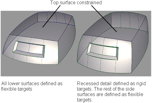
Flexible targets are surfaces, curves, or meshes that can have their shapes changed by applying transformations to the rig.
To add flexible targets, click this icon and select the geometry to assign as targets, then click Accept Targets. To remove targets, choose the Remove from Rig tool in the toolbox.

Rigid targets are surfaces, meshes, or curves. They transform (translate and/or rotate) along with the modification, but keep their shape; that is, the targets do not scale or shear.
To add rigid targets, click the icon and select the geometry, then click Accept Targets. To remove targets, choose the Remove from Rig tool in the toolbox.
Use the  on a target to open a pop-up menu that enables you to lock the movement direction for the rigid targets.

If Rigid is selected, the target is free to rotate and translate in all directions. Rigid Translate only allows translation to occur: the target is not rotated. Further restrictions can be used with the X, Y, and Z constraints, which allow translation to occur in only one specific world-space axis direction (note: this does not respect construction planes). You can also change the type of target from Rigid to Flexible, or vice-versa.

A predefined modifier is a pair of similarly parameterized geometries.

Constraints define a region of the model that should not be modified, and also delimit the range of modification. The continuity along the constraint can be fixed as positional or tangential. Using the to click a constraint opens a pop-up menu to change the continuity quality of the constraints. The default is for the constraints
to be tangentially continuous.


Clampers can help the software recognize regions of the model that should not be modified. These regions are usually defined by the constraints, but in some cases, the help of a clamper or clampers is needed. These regions can be identified with the help of the green and red dots that appear when setting constraints. These dots appear when Clamp Visualization is checked in the option box.
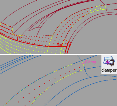
The region with green points is the region that is free to be modified. The region with red points is fixed, and will not change. To improve the visualization temporarily, pick a dot with the middle mouse button to make the colors more vivid.


Choose this tool to remove targets, modifiers, constraints, or clampers from the rig. You can pick constraints, modifiers, or targets, and clampers. The geometry picked for removal is highlighted in yellow. To confirm the removal, click the Remove Selected button in the lower right corner of the view. To cancel the operation, click Cancel.

When targets are added to the rig, they are duplicated. The shape modifications are performed with this duplicated geometry. To restore the original geometry and to delete the modified geometry and history, click Revert. Notice that the manipulated modifiers do not return to their status before the dynamic modeling.
Transformer Rig Options window
To see the Options window while outside the tool, first re-enter the tool by selecting Object Edit > Query Edit then select an object that has dynamic shape modeling history. Hold the key and click the Transformer Rig tool icon in the toolbox.
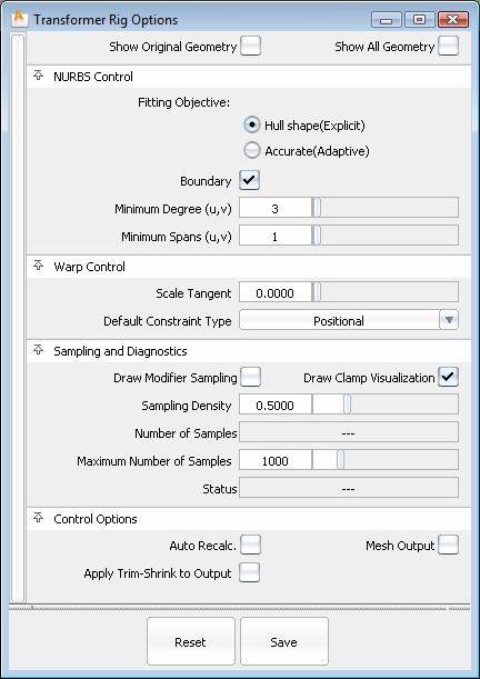
The fields in this section control the way the Transformer Rig tool modifies NURBS target surfaces. Settings in this window have no effect on meshes that were selected as targets. If all targets are meshes, or if Mesh Output is set, this section of the control window is hidden.
Hull Shape (Explicit) – Optimizes fitting for hull shape. This option allows for explicit control of minimum degree and spans. If the boundary field is checked, the fitting is optimized for patch boundaries.

Accurate (Adaptive) – Optimizes fitting for accuracy. This determines the minimum number of spans necessary for an accurate representation of the modified shape.
The Fitting Effort option has been reorganized to a pull-down menu with Low, Medium, High, and Custom values. If Custom is selected, a slider can be used to set the value precisely.
While it is not possible to give a true tolerance for gap continuity, the fitting effort is a number that points to the gap quality. The larger the number, the tighter the gap is between surfaces, and the longer a modification takes to execute. To influence the final maximum gap distance after the modification, increase or decrease the fitting effort. The Transformer Rig inserts more spans to achieve tighter gaps between surfaces, up to the maximum set in Max Surf Spans in Construction options.
The Fitting Effort option has a pull-down menu with Low, Medium, High, and Custom values. If Custom is selected, a slider can be used to set the value precisely.
The controls in this section can be used to adjust how the modifier and the constraints influence the target geometry.
The overall intent of the controls in this section is to help control the quality and performance of Transformer Rig modifications.
Some error conditions stop the deformation from proceeding. When a deformation cannot be applied, the outlines of target geometry are drawn with dotted lines.
Stress Exceeds Threshold: This error condition is triggered if there is too much stress in the shape modification, typically due to conflicting modifiers and constraints simultaneously forcing the surface to move and stay put. Red arrows point to the samples with too much stress. You can correct the condition by rearranging modifiers and constraints so that they do not conflict.
Too many samples. This error condition is triggered when the Sampling Density creates too many sample points. Sample points can be viewed by turning on the Draw Modifier Sampling check box. To correct the error, either increase the Maximum Number of Samples field, or reduce the number of samples by decreasing the Sampling Density field or eliminating unnecessary modifiers and constraints.
If checked, any changes in any field in the control box lead to an automatic update of the model display. If Auto Recalc is not checked, click the Go button in the active window to update the display after any changes. Normally, if you have a very large model that takes a long time to update, leave the Auto Recalc box unchecked.

If Auto Recalc. is on, the Go button is not shown. Any changes to the rig (parameters or constructors) cause the history to re-evaluate automatically and immediately.
If Auto Recalc. is off, the Go button is displayed. Any changes to the rig cause the Go button to be enabled, and when you click Go, the re-evaluation occurs. History itself exists the moment you enter the tool — not clicking the Go button does not change this, and you do not lose history by prematurely leaving the tool.
While a recalculation is occurring, a progress bar is shown on screen. If you feel the evaluation is taking longer than you
care to wait, you can cancel it by pressing the  key.
key.


