


This lesson shows you how to create a pair of twisting horns. It uses extrusions and transforms; it also demonstrates spline extrusion as a simple alternative to multiple extrusions.
Once again, apply a Symmetry modifier to mirror the edits you make to one half of the helmet.
 open helmet_03.max.
 select the helmet, and make sure the
  Modify panel is active. Click
  (Use NURMS) to turn it off.
Split the model in half and apply a Symmetry modifier:
 Polygon Modeling panel, activate
  (Polygon). Select the polygons on the left half of the helmet (from your point of view), and then press Delete.
On the Modify panel, you can toggle  (Show End Result) to make sure the helmet is mirrored correctly.
Polygon Modeling panel, click  (Previous Modifier) to go to the Editable Poly level.
Adjust vertices at the base of the horn:
Polygon Modeling panel, activate  (Vertex).
Edit panel Constraints group, activate
(Vertex).
Edit panel Constraints group, activate  (Constrain To Edge).
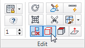
This ensures that the transform of any vertex will slide along the edges of the polygon to which it belongs.
 (Zoom Extents) to get a good view of the helmet.
 (Select And Move), then select a vertex in the upper region of the helmet and move it as shown in the next illustration.
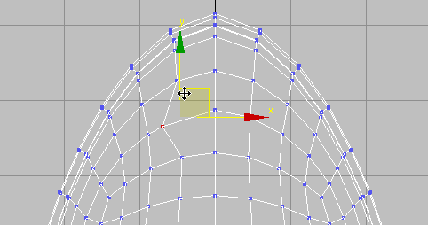
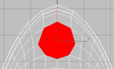
 move it as well. Also move the vertices above and below the central vertex. The goal is to create a symmetrical shape that
is roughly circular.
move it as well. Also move the vertices above and below the central vertex. The goal is to create a symmetrical shape that
is roughly circular.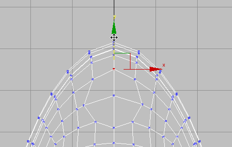 Edit panel, activate
  (Constrain To None).
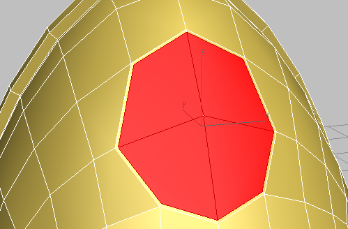
Select the vertex at the center of the circular group of polygons.
(Constrain To None).
Select the vertex at the center of the circular group of polygons.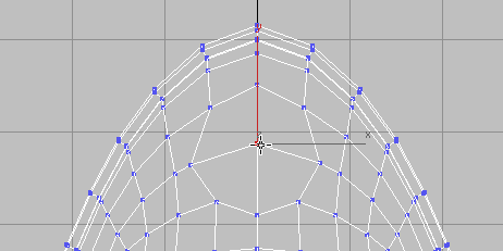 Polygon Modeling panel, Ctrl+click (Polygon).
This automatically selects all the polygons that share the vertex.
 Orbit so you can see all of the base of the horn.
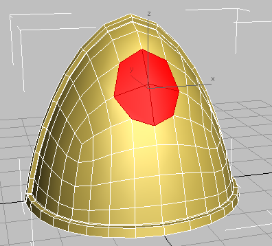
 (Inset).
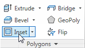
 (OK).
(OK).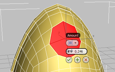
This creates an inset edge for the selected polygons.
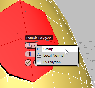
Use extrusion and bevel to create the socket for the horn:
 (Extrude).
 (OK).
(OK).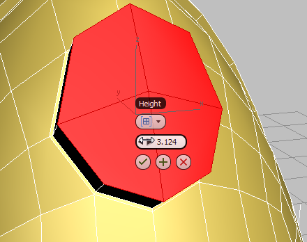
 (Bevel).
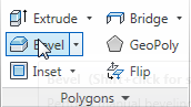 (OK).
(OK).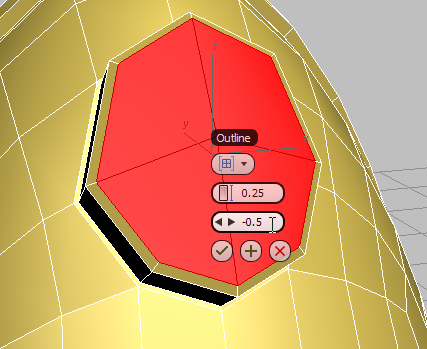
Helmet horn socket after first extrusion and bevel
(Inset).
(OK).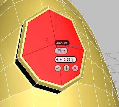 (Bevel).
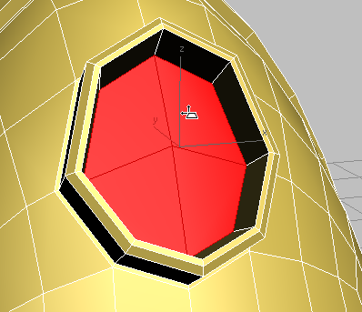
Horn socket after second inset and bevel
(Extrude) again, and drag away from the helmet until the polygons extend slightly beyond the socket. Click to end the extrude
operation.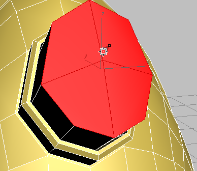
Helmet horn ready for spline-based extrusion
At this point, you could continue to create the horn by using the Move, Rotate, and Scale tools, coupled with the Extrude, Bevel, and Inset polygon tools. Instead, you will guide the extrusion by means of a path.
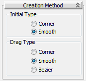
Draw a spline for extruding the horn:
 Create panel, click
  (Shapes), then on the Object Type rollout, click Line.
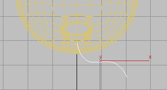 move the line along its Y axis until it is centered on the horn socket. Move it along the X axis too, if you need to.
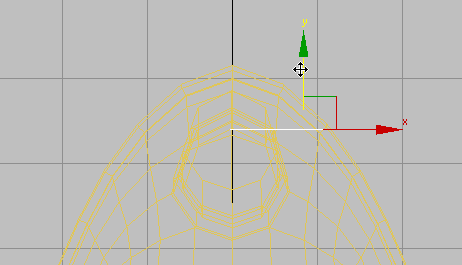 Modify panel Selection rollout, and activate
  (Vertex).
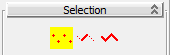
 Maximize the Perspective view and move the line’s vertices until they form the shape of the horn you want to create.
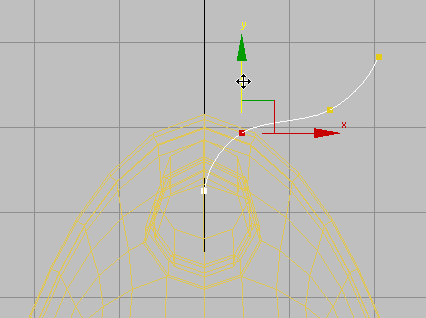 Double-check and refine your Line edits in the other viewports.
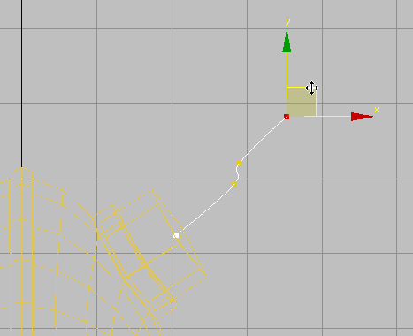
Left view
 (Vertex) once more to turn it off.
Select the helmet, then on the ribbon Polygon Modeling panel, click (Previous Modifier) to go to the Editable Poly level.
(Polygon), then click
(Vertex) once more to turn it off.
Select the helmet, then on the ribbon Polygon Modeling panel, click (Previous Modifier) to go to the Editable Poly level.
(Polygon), then click  (Show End Result) to turn it on.
drop-down panel, Shift+click Extrude On Spline.
(Show End Result) to turn it on.
drop-down panel, Shift+click Extrude On Spline.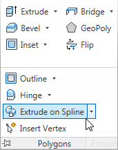
The caddy controls for spline extrusion are more numerous than for most caddies.
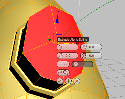
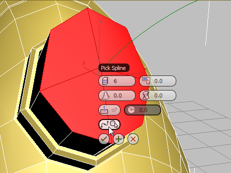
After you click the spline, 3ds Max grows horns, but these have no taper, yet.
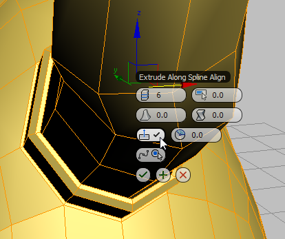
3ds Max aligns the spline to the normals of the original faces, making the horns more perpendicular to the rest of the helmet. This might or might not be a good effect, depending on the spline you drew.
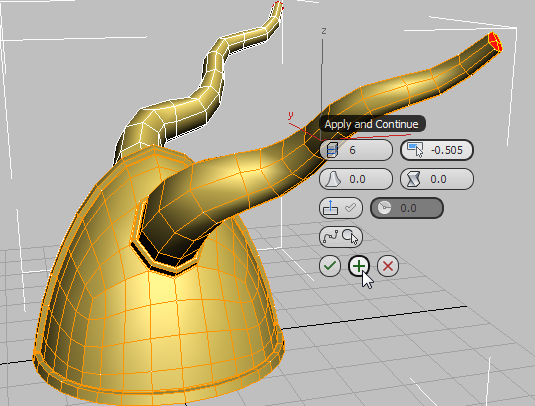
 (Apply And Continue).
3ds Max extrudes the horns still further. This is easier to see in other viewports, but you can also navigate the Perspective view, as shown in this illustration.
 (OK) to finalize these changes and finish creating the horns.
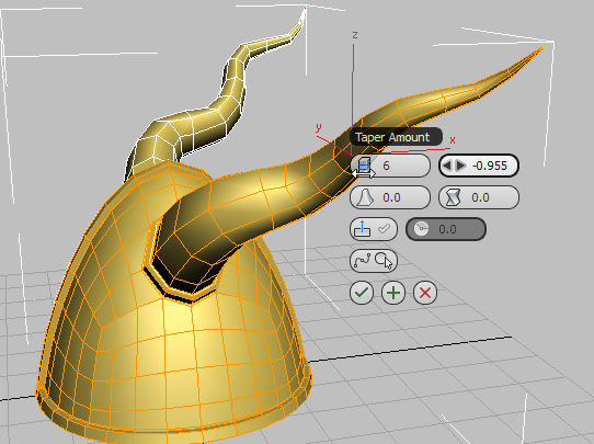
By extruding the horns along a path, you saved yourself a great deal of back-and-forth between the transform and polygon modeling tools.
Polygon Modeling panel, click  (Polygon) again to turn it off.
Make the helmet a single object once again:
 (Use NURMS) is off. NURMS smoothing needs to be off before you transform the helmet into an Editable Poly: Otherwise, you
wind up with a model that has far too many faces.
Convert To Editable Poly, then press F4 to turn off edged faces.
(Use NURMS) is off. NURMS smoothing needs to be off before you transform the helmet into an Editable Poly: Otherwise, you
wind up with a model that has far too many faces.
Convert To Editable Poly, then press F4 to turn off edged faces.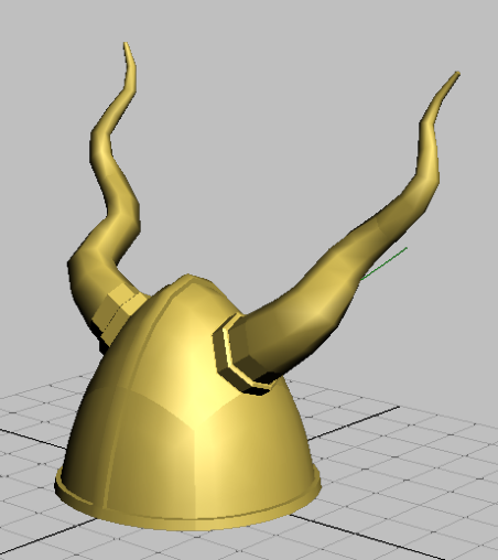
The Symmetry modifier is removed and all the mirrored polygons are integrated into the model.