


Now that you have set up the stack and the color of selected polygons, you are ready to turn the plane of the façade into a three-dimensional model.
Continue working on your scene from the previous lesson, or  open \modeling\facades\facade_modeling_02.max.
 select the façade, go to the
  Modify panel, and make sure that
  (Show End Result) is on for all three levels of the stack.
 (Maximize Viewport Toggle) (or click Alt+W) to maximize the Front viewport.
Modify panel. In the modifier stack, click to activate the Editable Poly level.
(Maximize Viewport Toggle) (or click Alt+W) to maximize the Front viewport.
Modify panel. In the modifier stack, click to activate the Editable Poly level.
 (Graphite Modeling Tools (Open)). If you need to, click the ribbon’s
  expand/collapse icon until the full-size ribbon panels display.
 (Edge) to turn on the Edge sub-object level.
 move it downward to hide the roof.
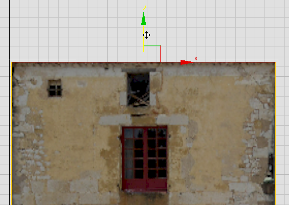
 Zoom the viewport so you have a good view of the three windows in the upper portion of the wall.
 Edit panel, click to turn on
  (SwiftLoop).
The SwiftLoop tool adds edges to the Editable Poly surface by drawing a “loop” from one edge to another.
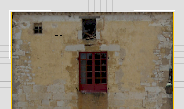
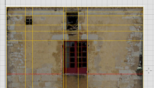
Add edges for the lintel beam and the doorways:
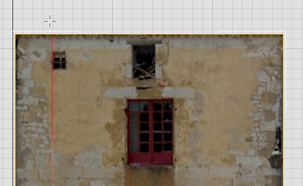
 Pan down to get a good view of the doorway area.
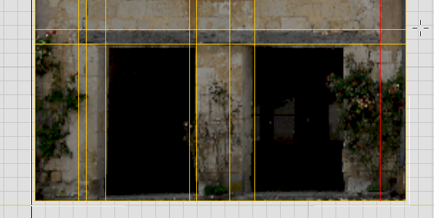
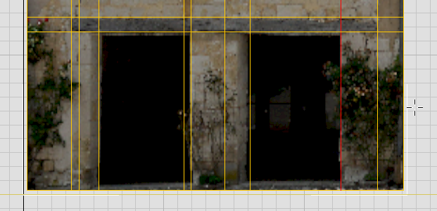
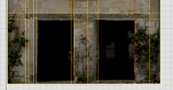
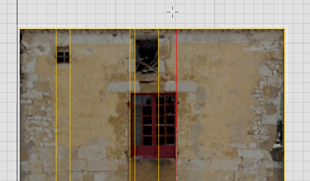
Loop for the angle of the left doorway’s left-hand doorjamb
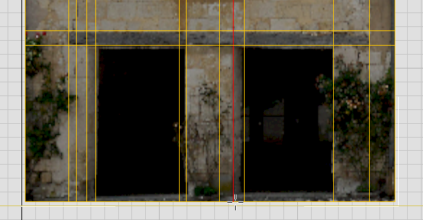
Loop for the angle of the right doorway’s left-hand doorjamb
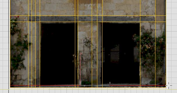
Now you have most of the edges you need to add 3D detail to the façade.
Add depth to the top center window:
 Edge to return to the top, object level.
 click to select the Ground object in the background, then right-click and from the quad menu, choose Hide Selection.
 Zoom and pan to get a good view of the windows in the upper portion of the wall.
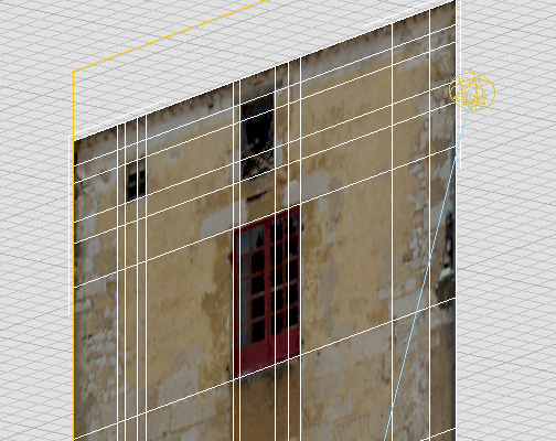 Select Facade1 again.
 Polygon to go to the Polygon sub-object level.
Click and Ctrl+click to select the three faces of the top center window.
Polygon to go to the Polygon sub-object level.
Click and Ctrl+click to select the three faces of the top center window.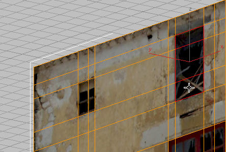 Polygons panel, click the drop-down arrow next to the
  Extrude button, and choose Extrude Settings.
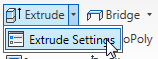
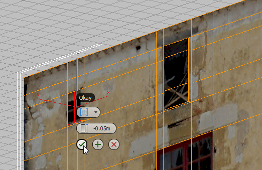
3ds Max displays an interactive manipulator called a “caddy.”
 (OK: the check-mark icon at the bottom of the caddy) to complete the extrusion.
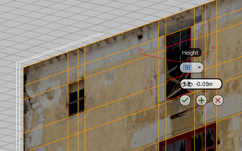
Add depth to the other two windows:
Click and Ctrl+click to select the two polygons of the small window at the upper left. (Extrude).
Shift+click is a shortcut way to display the caddy for a modeling tool.
 (OK) so the small window matches its larger neighbor.
Click and Ctrl+click to select the four polygons of the main window in the center of the wall.
(OK) so the small window matches its larger neighbor.
Click and Ctrl+click to select the four polygons of the main window in the center of the wall.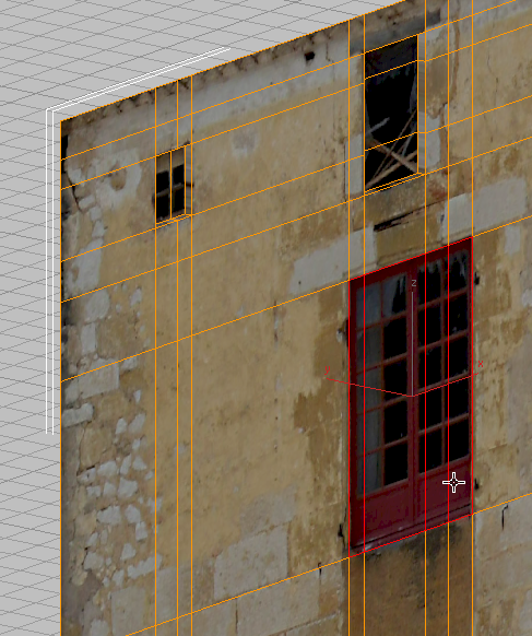 (Extrude).
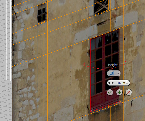 (OK).
(OK).
Now the windows for Facade1 are done.
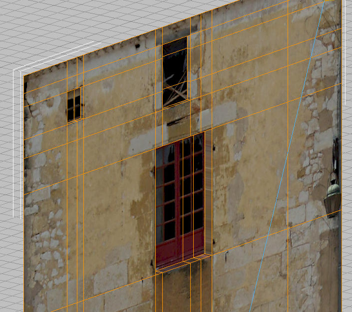
This completes the modeling of the upper portion of the wall.
 (Next Modifier) and
  (Previous Modifier). These move to the geometry level as well as to modifiers.