Command entry:
Select a shape.


Modify panel
Modifier List
Renderable Spline
The Renderable Spline modifier lets you set the renderable properties of a spline object without needing to convert the object
to an editable spline. This is particularly useful with splines you have linked to from AutoCAD. It also lets you apply the
same rendering properties to multiple splines at once.
NoteThis modifier cannot be applied to NURBS curves.
Interface
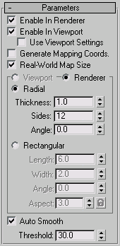
- Enable In Renderer
-
When on, the shape is rendered as a 3D mesh using the Radial or Rectangular parameters set for Renderer.
- Enable In Viewport
-
When on, the shape is displayed in the viewport as a 3D mesh using the Radial or Rectangular parameters set for Renderer.
- Use Viewport Settings
-
Lets you set different parameters for viewport display and rendering, and displays the mesh generated by the Viewport settings
in the viewports. Available only when Enable in Viewport is on.
- Generate Mapping Coords
-
Turn this on to apply mapping coordinates. Default=off.
3ds Max generates the mapping coordinates in the U and V dimensions. The U coordinate wraps once around the spline; the V coordinate
is mapped once along its length. Tiling is achieved using the Tiling parameters in the applied material. For more information,
see Mapping Coordinates.
- Real-World Map Size
-
Controls the scaling method used for texture mapped materials that are applied to the object. The scaling values are controlled
by the Use Real-World Scale settings found in the applied material's Coordinates rollout. Default=on.
- Viewport
-
Choose this to specify Radial or Rectangular parameters for the shape as it will display in the viewport when Enable In Viewport
is on. Available only when Use Viewport Settings is on
- Renderer
-
Choose this to specify Radial or Rectangular parameters for the shape as it will display when rendered or displayed in the
viewport when Enable in Viewport is turned on.
- Radial
-
Displays the spline as a 3D object with a circular cross-section.
- Specifies the cross-section diameter. Default=1.0. Range=0.0 to 100,000,000.0.
- Sets the number of sides for the spline mesh in the viewports or renderer. For example, a value of 4 produces a square cross-section.
- Adjust the rotational position of the cross section in the viewports or renderer. For example, if you have a square cross
section you can use Angle to position a “flat” side down.
- Rectangular
-
Displays the spline as a 3D object with a rectangular cross-section.
- Specifies the size of the cross–section along the local Y axis.
- Specifies the size of the cross–section along the local X axis.
- Adjusts the rotational position of the cross-section in the viewport or renderer. For example, if you have a square cross-section
you can use Angle to position a "flat" side down.
- Sets the aspect ratio for rectangular cross-sections. The Lock check box lets you lock the aspect ratio. When Lock is turned
on, Width is locked to Depth that results in a constant ratio of Width to Depth.
- Auto Smooth
-
When on, the spline is auto-smoothed using the smoothing angle specified by the Threshold setting. Auto Smooth sets the smoothing
based on the angle between spline segments. Any two adjacent segments are put in the same smoothing group if the angle between
them is less than the threshold angle.
NoteTurning Auto Smooth on for every situation does not always give you the best smoothing quality. Altering the Threshold angle
may be necessary or turning Auto Smooth off may produce the best results.
- Threshold
-
Specifies the threshold angle in degrees. Any two adjacent spline segments are placed in the same smoothing group if the angle
between them is less than the threshold angle.