A polygon is a closed sequence of three or more edges connected by a surface. Polygons provide the renderable surface of editable poly objects.
At the Editable Poly (Polygon) sub-object level, you can select single and multiple polygons and transform them using standard
methods. At the Element sub-object level you can select and edit groups of contiguous polygons. For further distinctions between
polygon and element, see Editable Poly  Selection rollout. This topic covers the Edit Polygons/Elements rollout and Edit Geometry rollout functions for these sub-object types; for
other controls, see Editable Poly.
Selection rollout. This topic covers the Edit Polygons/Elements rollout and Edit Geometry rollout functions for these sub-object types; for
other controls, see Editable Poly.
See Editable Poly Selection rollout for information on the Selection rollout settings.
Soft Selection controls apply a smooth falloff between selected sub-objects and unselected ones. When Use Soft Selection is on, unselected sub-objects near your selection are given partial selection values. These values are shown in the viewports by means of a color gradient on the vertices, and optionally on the faces. They affect most types of sub-object deformations, such as the Move, Rotate, and Scale functions, as well as any deformation modifiers (such as Bend) applied to the object. This provides a magnet-like effect with a sphere of influence around the selection.
For more information, see Soft Selection Rollout.
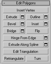
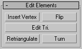
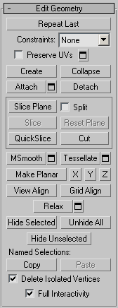
Edit Polygons/Elements rollout
At the Element sub-object level, this rollout includes commands that are common to both polygons and elements. At the Polygon level, it contains those as well as a number more that are unique to polygons. The commands available at both levels are Insert Vertex, Flip, Edit Triangulation, Retriangulate, and Turn.
Lets you subdivide polygons manually. Applies to polygons, even if at the element sub-object level.
After turning on Insert Vertex, click a polygon to add a vertex at that location. You can continue subdividing polygons as long as the command is active.
To stop inserting vertices, right-click in the viewport, or click Insert Vertex again to turn it off.
Lets you perform manual extrusion via direct manipulation in the viewport. Click this button, and then drag vertically on any polygon to extrude it.
Extruding polygons moves them along a normal and creates new polygons that form the sides of the extrusion, connecting the selection to the object.
Following are important aspects of polygon extrusion:
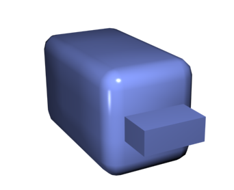
Chamfer box showing extruded polygon
 Extrude Settings
Opens the Extrude Polygons caddy, which lets you perform extrusion via interactive manipulation.
If you click this button after performing an extrusion, the same extrusion is performed on the current selection as a preview and the dialog opens with Extrusion Height set to the amount of the last manual extrusion.
Lets you increase or decrease the outside edge of each contiguous group of selected polygons.
Outline is often used after an extrusion or bevel to adjust the size of the extruded faces. It doesn't scale the polygons; only changes the size of the outer edge. For example, in the following illustration, note that the sizes of the inner polygons remain constant.
Outline SettingsOpens the Outline Polygons caddy, which lets you perform outlining by a numeric setting.
For details on using the caddy controls, see The Caddy Interface.
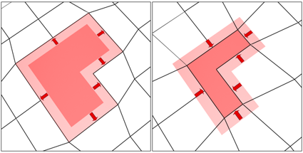
Lets you perform manual beveling via direct manipulation in the viewport. Click this button, and then drag vertically on any polygon to extrude it. Release the mouse button and then move the mouse vertically to outline the extrusion. Click to finish.
Polygon beveled outward (left) and inward (right)
Bevel SettingsOpens the Bevel caddy, which lets you perform beveling via interactive manipulation.
If you click this button after performing a bevel, the same bevel is performed on the current selection as a preview and the dialog opens with the same settings used for the previous bevel.
Performs a bevel with no height; that is, within the plane of the polygon selection. Click this button, and then drag vertically on any polygon to inset it.
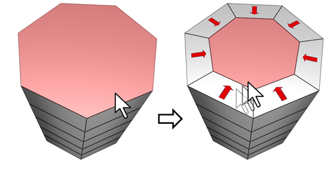
Inset works on a selection of one or more polygons. As with Outline, only the outer edges are affected.
Inset SettingsOpens the Inset caddy, which lets you inset polygons via interactive manipulation.
If you click this button after performing a manual inset, the same inset is performed on the current selection as a preview and the dialog opens with Inset Amount set to the amount of the last manual inset.
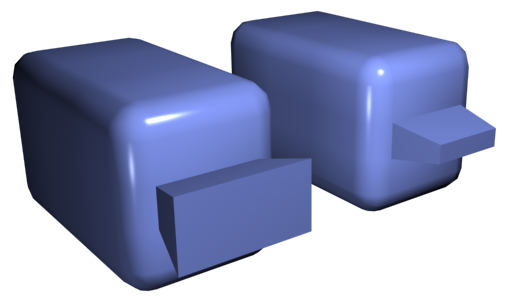
Connects two polygons or polygon selections on an object with a polygon “bridge.” There are two ways to use Bridge in Direct Manipulation mode (that is, without opening the Bridge Settings dialog):
Using Bridge at the Polygon level
Bridge SettingsOpens the Bridge Polygons caddy, which lets you connect pairs of polygon selections via interactive manipulation.
Lets you perform a manual hinge operation via direct manipulation in the viewport. Make a polygon selection, click this button, and then drag vertically on any edge to hinge the selection. The mouse cursor changes to a cross when over an edge.
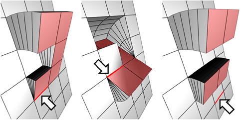
The hinge edge needn't be part of the selection. It can be any edge of the mesh. Also, the selection needn't be contiguous.
Hinging polygons rotates them about an edge and creates new polygons that form the sides of the hinge, connecting the selection to the object. It's essentially an extrusion with rotation, with the exception that, if the hinge edge belongs to a selected polygon, that side is not extruded. The manual version of Hinge From Edge works only with an existing polygon selection.
Hinge SettingsOpens the Hinge From Edge caddy, which lets you hinge polygons via interactive manipulation.
If you click this button after performing a manual hinge, the dialog opens with Angle set to the extent of the last manual hinge.
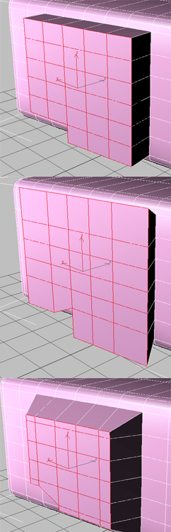
Extrudes the current selection along a spline.
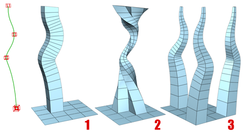
You can extrude a single polygon (1) or a selection of contiguous (2) or non-contiguous polygons (3). Extrusion 2 uses Taper Curve and Twist (available via Settings). Extrusion 3 uses Taper Amount; each extrusion has a different curve rotation.
Make a selection, click Extrude Along/On Spline, and then select a spline in the scene. The selection is extruded along the spline, using the spline's current orientation, but as though the spline's start point were moved to the center of each polygon or group.
Extrude Along Spline SettingsOpens the Extrude Along Spline caddy, which lets you extrude along splines via interactive manipulation.
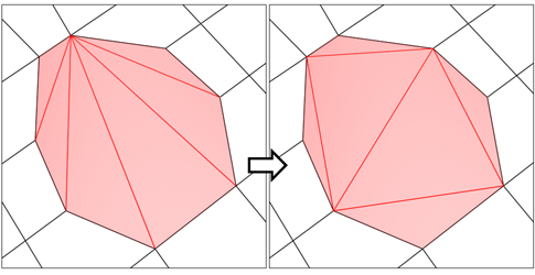
Lets you modify how polygons are subdivided into triangles by drawing internal edges.
In Edit Triangulation mode, you can see the current triangulation in the viewport, and change it by clicking two vertices on the same polygon.
To manually edit triangulation, turn on this button. The hidden edges appear. Click a polygon vertex. A rubber-band line appears, attached to the cursor. Click a non-adjacent vertex to create a new triangulation for the polygon.
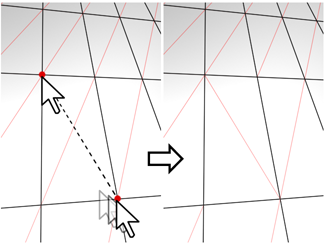
Lets you modify how polygons are subdivided into triangles by clicking diagonals. When you activate Turn, the diagonals become visible as dashed lines in wireframe and edged-faces views. In Turn mode, click a diagonal to change its position. To exit Turn mode, right-click in the viewport or click the Turn button again.
Each diagonal has only two available positions at any given time, so clicking a diagonal twice in succession simply returns it to its original position. But changing the position of a nearby diagonal can make a different alternate position available to a diagonal.
For more information on how to use Turn with the enhanced Cut tool, see this procedure.
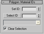
Lets you assign a particular material ID number to selected polygons for use with multi/sub-object materials and other applications. Use the spinner or enter the number from the keyboard. The total number of available IDs is 65,535.
This drop-down list shows the names of sub-materials if an object has a Multi/Sub-Object material assigned to it. Click the drop arrow and choose a sub-material from the list. The sub-objects that are assigned that material are selected. If an object does not have a Multi/Sub-Object material assigned, the name list is unavailable. Likewise, if multiple objects are selected that have an Edit Patch, Edit Spline, or Edit Mesh modifier applied, the name list is inactive.
Polygon: Smoothing Groups rollout
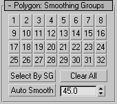
Use these controls to assign selected polygons to different smoothing groups, and to select polygons by smoothing group.
To assign polygons to one or more smoothing groups, select the polygons, and then click the number(s) of the smoothing group(s) to assign them to.
Displays a dialog that shows the current smoothing groups. Select all polygons that belong to a group by clicking the corresponding numbered button and clicking OK.
If Clear Selection is on, any previously selected polygons are first deselected. If Clear Selection is off, the new selection is added to any existing selection.
Polygon: Vertex Colors rollout
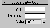
Use these controls to assign the color, illumination color (shading), and alpha (transparency) values of vertices on selected polygons or elements.
For information about the Subdivision Surface rollout settings, see Subdivision Surface Rollout (Polymesh).
Subdivision Displacement rollout
For information about the Subdivision Displacement rollout settings, see Subdivision Displacement Rollout (Polymesh).
Paint Deformation lets you stroke elevated and indented areas directly onto object surfaces. For more information, see Paint Deformation Rollout (Polymesh).


 Modify panel