Command entry:
Create panel


(Shapes)
NURBS Curves
Point Curve button
Command entry:Create menu
NURBS
Point Curve
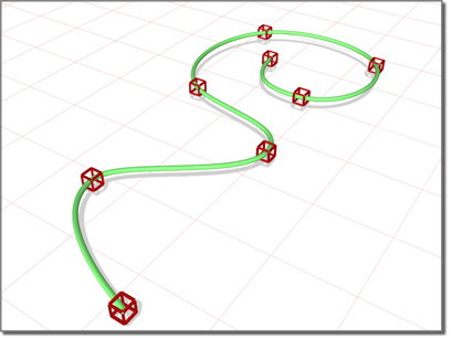
Point curves are NURBS curves whose points are constrained to lie on the curve.
A point curve can be the basis of a full NURBS model.
Drawing Three-Dimensional Curves
When you create a point curve, you can draw it in three dimensions. There are two ways to do this:
- Draw In All Viewports: This toggle lets you use any viewport to draw the curve, enabling you to draw three dimensionally.
- Using Ctrl to drag points: While you draw a curve, you can use the Ctrl key to drag a point off of the construction plane.
With the Ctrl–key method, further mouse movement lifts the latest point off the construction plane. There are two ways to use this:
While you are offsetting the point, a red dotted line is drawn between the original point on the construction plane and the
actual point offset from the plane. You can move the mouse into an inactive viewport, in which case 3ds Max sets the height of the point using the point's Z axis in the inactive viewport. This lets you set the height of the point
with accuracy.
Snaps also work when you change the height of a point. For example, if you turn on Point snapping, you can set a point to have
the same height as another point by snapping to that other point in an inactive viewport.
Procedures
To create a NURBS point curve:
- Go to the Create panel.
- Activate (Shapes), and choose NURBS Curves from the drop-down list.
- Turn on Point Curve.
- In a viewport, click and drag to create the first point, as well as the first curve segment. Release the mouse button to add
the second point. Each subsequent location you click adds a new point to the curve. Right-click to end curve creation.
NoteIf you begin the curve by clicking without dragging, this also creates the curve's first point. However, if you release the
mouse button more than five pixels away from where you initially pressed it, this creates an additional point.
While you are creating a point curve, you can press Backspace to remove the last point you created, and then previous points in reverse order.
If Draw In All Viewports is on, you can draw in any viewport, creating a 3D curve.
To lift a point off the construction plane, use the Ctrl key as described earlier in this topic under "Drawing Three-Dimensional Curves."
As with splines, if you click over the curve's initial point, a Close Curve dialog is displayed. This dialog asks whether you want the curve to be closed. Click No to keep the curve open or Yes to close the
curve. (You can also close a curve when you edit it at the Curve sub-object level.) When a closed curve is displayed at the
Curve sub-object level, the initial point is displayed as a green circle, and a green tick mark indicates the curve's direction.
- Adjust the curve's creation parameters.
- (Optional.) To add a new NURBS curve sub-object, you can turn off the Start New Shape check box, and then repeat the preceding
steps.
Interface
The creation parameters are the same for both point curves and CV curves.
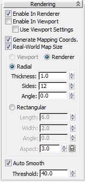
Rendering rollout
Lets you turn on and off the renderability of the curve, specify its thickness in the rendered scene, and apply mapping coordinates.
Render parameters can be animated. For example, you can animate the number of sides.
- Enable In Renderer
-
When on, the shape is rendered as a 3D mesh using the Radial or Rectangular parameters set for Renderer.
- Enable In Viewport
-
When on, the shape is displayed in the viewport as a 3D mesh using the Radial or Rectangular parameters set for Renderer.
- Use Viewport settings
-
Lets you set different rendering parameters, and displays the mesh generated by the Viewport settings. Available only when
Enable in Viewport is turned on.
- Generate Mapping Coords
-
Turn this on to apply mapping coordinates. Default=off.
The U coordinate wraps once around the thickness of the spline; the V coordinate is mapped once along the length of the spline.
Tiling is achieved using the Tiling parameters in the material itself.
- Real-World Map Size
-
Controls the scaling method used for texture mapped materials that are applied to the object. The scaling values are controlled
by the Use Real-World Scale settings found in the applied material's Coordinates rollout. Default=on.
- Viewport
-
Turn this on to specify Radial or Rectangular parameters for the shape as it will display in the viewport when Enable in Viewport
is turned on.
- Renderer
-
Turn this on to specify Radial or Rectangular parameters for the shape as it will display when rendered or viewed in the viewport
when Enable in Viewport is turned on.
- Radial
-
Displays the 3D mesh as a cylindrical object.
- Thickness
-
Specifies the diameter of the viewport or rendered spline mesh. Default=1.0. Range=0.0 to 100,000,000.0.
- Sides
-
Sets the number of sides (or facets) for the spline mesh n the viewport or renderer. For example, a value of 4 results in
a square cross section.
- Angle
-
Adjusts the rotational position of the cross-section in the viewport or renderer. For example, if the spline mesh has a square
cross section you can use Angle to position a "flat" side down.
- Rectangular
-
Displays the spline's mesh shape as rectangular.
- Aspect
-
Sets the aspect ratio for rectangular cross-sections. The Lock check box lets you lock the aspect ratio. When Lock is turned
on, Width is locked to Depth that results in a constant ratio of Width to Depth.
- Length
-
Specifies the size of the cross–section along the local Y axis.
- Width
-
Specifies the size of the cross–section along the local X axis.
- Angle
-
Adjusts the rotational position of the cross-section in the viewport or renderer. For example, if you have a square cross-section
you can use Angle to position a "flat" side down.
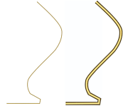
- Auto Smooth
-
If Auto Smooth is turned on, the spline is auto-smoothed using the threshold specified by the Threshold setting below it.
Auto Smooth sets the smoothing based on the angle between spline segments. Any two adjacent segments are put in the same smoothing
group if the angle between them is less than the threshold angle.
- Threshold
-
Specifies the threshold angle in degrees. Any two adjacent spline segments are put in the same smoothing group if the angle
between them is less than the threshold angle.
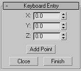
Keyboard Entry rollout
The Keyboard Entry rollout lets you create a NURBS curve by typing. Use the Tab key to move between the controls in this rollout. To click a button from the keyboard, press Enter while the button is active.
- X, Y, and Z
-
Let you enter the coordinates of the next point to add.
- Add Point
-
Adds the point to the curve.
- Close
-
Ends creation of the curve and creates a segment between the last point and the initial point to close the curve.
- Finish
-
Ends creation of the curve, leaving it open.
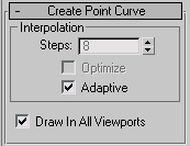
Create Point Curve rollout
This rollout contains the controls for curve approximation.
Interpolation group
The controls in this group box change the accuracy and type of curve approximation used to generate and display the curve.
- Draw In All Viewports
-
Lets you use any viewport while you are drawing the curve. This is one way to create a 3D curve. When off, you must finish
drawing the curve in the viewport where you began it. Default=on.
While Draw In All Viewports is on, you can also use snaps in any viewport.