Command entry:
Select a shape.


Modify panel
Modifier List
Bevel
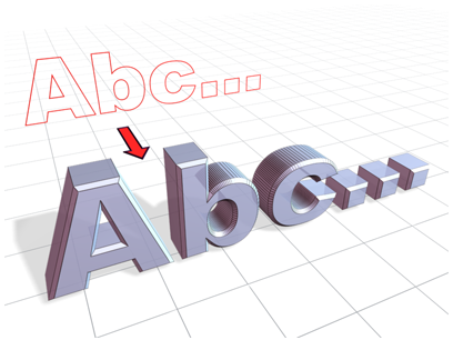
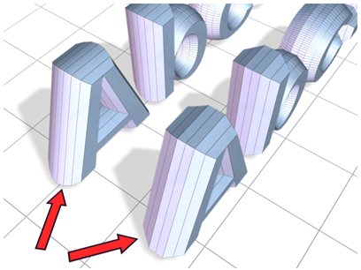
The Bevel modifier extrudes shapes into 3D objects and applies a flat or round bevel to the edges. A common use for this modifier
is to create 3D text and logos, but you can apply it to any shape.
Bevel takes a shape as the base of a 3D object. You then extrude the shape up to four levels and assign an outline amount
for each level.
Procedures
Example: To create beveled text:
This example produces typical 3D beveled text, with equal bevels in front and back.
- Create text using default settings.
Font=Arial, Size=100.0.
- Apply the Bevel modifier.
- Type -1.0 in the Start Outline field.
- For Level 1, do the following:
- Type 5.0 for Height.
- Type 2.0 for Outline.
- Turn on Level 2, and do the following:
- Type 5.0 for Height.
- Type 0.0 for Outline.
- Turn on Level 3 and do the following:
- Type 5.0 for Height.
- Type –2.0 for Outline.
- If needed, turn on Keep Lines From Crossing.
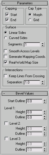
Interface
Capping group
You can determine whether or not the beveled object is capped at either end with the check boxes in the Capping group.
- Start
-
Caps the end with the lowest local Z value (bottom) of the object. When turned off, the bottom is open.
- End
-
Caps the end with the highest local Z value (top) of the object. When turned off, the end is left open.
Cap Type group
Two radio buttons set the type of cap used.
- Morph
-
Creates cap faces suitable for morphing.
- Grid
-
Creates cap faces in a grid pattern. This cap type deforms and renders better than morph capping.
Surface group
Controls the side curvature, smoothing, and mapping of the surface.
The first two radio buttons set the interpolation method used between levels; a numeric field sets the number of segments
to interpolate.
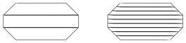
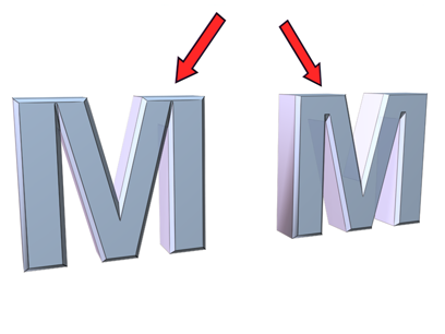
- Linear Sides
-
When active, segment interpolation between levels follows a straight line.
- Curved Sides
-
When active, segment interpolation between levels follows a Bezier curve. For visible curvature, use multiple segments with
Curved Sides.
- Segments
-
Sets the number of intermediate segments between each level.
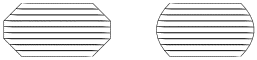
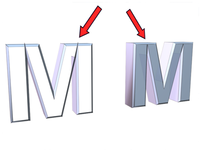
- Smooth Across Levels
-
Controls whether smoothing groups are applied to the sides of a beveled object. Caps always use a different smoothing group
than the sides.
- When turned on, smoothing groups are applied to the sides. The sides appear rounded.
- When turned off, smoothing groups are not applied. The sides appear as flat bevels.
- Generate Mapping Coordinates
-
When turned on, mapping coordinates are applied to the beveled object.
- Real-World Map Size
-
Controls the scaling method used for texture mapped materials that are applied to the object. The scaling values are controlled
by the Use Real-World Scale settings found in the applied material's Coordinates rollout. Default=on.
Intersections group
Prevents sharp corners from overlapping neighboring edges.
Bevel works best with rounded shapes or shapes with corners greater than 90 degrees. Acute angles (less than 90 degrees) produce
extreme bevels and often overlap nearby edges.
- Keep Lines From Crossing
-
Prevents outlines from crossing over themselves. This is accomplished by inserting extra vertices in the outline and replacing
sharp corners with a flat line segment.
- Separation
-
Sets the distance to be maintained between edges. The minimum value is 0.01.
Bevel Values rollout
Contains the parameters that set the height and bevel amount of up to four levels.
A beveled object requires a minimum of two levels: a start and an end. You add more levels to vary the amount and direction
of bevel from start to end.
You can think of bevel levels as layers on a cake. The Start Outline is the bottom of the cake and the Level 1 parameters
define the height and size of the first layer.
Turning on Level 2 or Level 3 adds another layer to the beveled object with the height and outline specifying the amount of
change from the previous level.
The last level on is always the top of the object.
You must always set the Level 1 parameters.
- Start Outline
-
Sets the distance the outline is offset from the original shape. A non-zero setting changes the original shape's size.
- Positive values make the outline larger.
- Negative values make the outline smaller.
- Level 1
-
Includes two parameters that indicate the change from the Start level.
- Height
-
Sets the distance of Level 1 above the Start level.
- Outline
-
Sets the distance to offset the Level 1 outline from the Start Outline.
Levels 2 and Level 3 are optional and allow you to change the bevel amount and direction.
- Level 2
-
Adds a level after Level 1.
- Height
-
Sets the distance above Level 1.
- Outline
-
Sets the offset distance of the Level 2 outline from Level 1.
- Level 3
-
Adds a level after the previous level. If Level 2 is not on, Level 3 is added after Level 1.
- Height
-
Sets the distance above the previous level.
- Outline
-
Sets the offset distance of Level 3 from the previous level.
Traditional beveled text uses all levels with these typical conditions:
- Start Outline can be any value, usually 0.0.
- Level 1 Outline is a positive value.
- Level 2 Outline is 0.0. No change from Level 1.
- Level 3 Outline is the negative of Level 1. Returns Level 3 to the same size as the Start Outline.