Command entry:
Utilities panel

Utilities rollout
Motion Capture button
The Motion Capture utility drives your animation using peripheral devices, such as MIDI keyboards, joysticks, and the mouse.
While driving the animation, you can record it in real time.
The motion capture system in 3ds Max is handled in the following way:
- In Track View, assign motion capture animation controllers to the specific tracks you want controlled by external devices.
- After assigning the Motion Capture controller, open the Properties dialog for the track and bind the type of peripheral device(s).
As an example, the Rotation Motion Capture controller has three rotational axes to which you can bind one device each.
- After binding devices, adjust their settings and parameters in the lower portion of the Track Properties dialog. These controls
vary depending on the type of device.
- On the Utilities panel, open the Motion Capture utility. You can test and record your motion for any combination of tracks
over any range of frames.
The following motion-capture devices are included with 3ds Max:
Mouse Input Device rollout
Keyboard Input Device rollout
Joystick Input Device rollout
MIDI Device rollout
Procedures
To assign a Motion Capture controller to tracks:
The first step in using motion capture is to assign motion-capture controllers to the tracks you want.
- In the Track View hierarchy, highlight the Transform track you want.
- Choose Controller Assign.
3ds Max opens the Assign Controller dialog.
- Choose Motion Capture (might start with “Position,” “Float,” “Scale,” or other), and then click OK.
A Motion Capture dialog is displayed. Its title bar includes the name of the object and the track to which the controller
is assigned.
If a Data dialog opens instead, close it, right-click the track name, and choose Properties.
When you assign a Motion Capture controller, the previously assigned controller is maintained as a child of the Motion Capture
controller. This lets you continue to adjust the object using standard transform controls, while still making motion-capture
control available.
To bind and adjust devices:
- After assigning a Motion Capture controller, determine the type of device that will drive the motion.
Depending on the type of controller, you might be able to bind one or more devices. For example, a Rotation Motion Capture
controller can have three devices, one for each axis of rotation. On the other hand, a controller for the radius of a cylinder
would have only one device to control the radius value.
- Bind the devices in the Properties dialog for the track.
To specify a device:
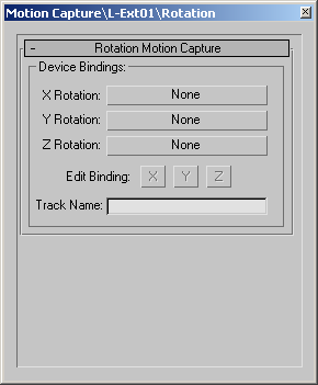
- Click the Properties button while the Rotation track is selected.
The Properties dialog for rotation motion capture includes three binding buttons (one for each axis.)
- Click the Y Rotation button. In the resulting dialog, choose Mouse Input Device, and click OK.
The lower half of the Properties dialog display controls specific to the new device. Assuming this is a segment that isn't
attached to another object, you want the horizontal mouse movement.
- Under Mouse Input, choose Horizontal.
The Scale spinner lets you adjust the relative effect of the mouse movement to the rotation. Flip reverses the rotational
direction with respect to the mouse movement.
Example: To set up the Joystick controller to move a Free camera:
You set up the Joystick controller to move a Free Camera around on the XY plane. The Y movement of the joystick will affect
the camera's forward and backward movement, and the X movement of the joystick will rotate the camera. You'll use Increment
Based On Direction to allow the Y movement to be local to the camera rather than to the world.
- Create a Free camera in the Front viewport.
- In Track View, assign a Rotation Motion Capture controller to the Rotation track of the camera.
- Right-click in the Rotation track to display the Motion Capture properties dialog.
- Click the button beside Z Rotation, and assign a Joystick Input Device.
- Under Joystick Axis, choose the X option (if it's not already chosen).
- Check Accumulate so that the rotation won't return to zero each time you release the joystick.
Example: To set up the Position controllers of a camera for moving with a joystick:
The rotation of the camera about its world Z axis will be controlled by the X motion of the joystick. You'll set up the Position
controllers of the camera to move the camera forward and back with the Y motion of the joystick.
- Assign a Position Motion Capture controller to the camera's Position track, and access its Properties dialog.
- Assign a Joystick Input Device to both the X Position and Y Position buttons.
- Click the Edit Binding X button, and then choose the Y option under Joystick Axis.
- Check Accumulate.
- Click the Edit Binding Y button, and also choose Y under Joystick Axis.
- Check Accumulate.
The Y motion of the joystick will now affect both the X and Y positions of the camera.
Example continued: To add the increment based on direction options:
If you tested the camera motion at this point, moving the joystick forward or backward along the Y would produce a diagonal
motion because the Position tracks would receive equal amounts of X and Y values. Adding the Increment Based On Direction
options will change this.
- Click the X Edit Binding button.
- Under Increment Based On Direction, click the button beside Controller.
A dialog appears with a list of controllers.
- Find and select the Rotation Motion Capture controller for the camera.
- Set the Direction option to Z (the local axis along which the direction points).
- Set the Component option to X (matching the Edit Binding button).
- Click the Y Edit Binding button.
- Click the button beside Controller, and assign the Rotation Motion Capture controller.
- Set the Direction option to Z, then set the Component option to Y.
- Open the Motion Capture utility, turn on both tracks in the list, click the Test button, and move the camera while observing
it in the Top viewport.
As you move the joystick in the Y direction, the camera moves forward or backward. Moving the joystick in the X direction
rotates the camera, but then, as you continue moving the joystick in the Y direction, the camera moves forward and back along
its local axis.
Interface
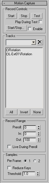
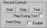
Record Controls group
Tests and records your animation. The first three buttons let you control the recording directly, while the Start/Stop button
lets you use a MIDI device to control the recording.
- Start
-
Starts a recording using the values set under Record Range below the Track list.
- Stop
-
Stops the recording before the Out frame is reached. You can also stop a recording by pressing Esc, or by pressing the right mouse button.
- Test
-
Tests your motion. No recording takes place. Exit by clicking Test again, pressing Esc, or clicking the right mouse button.
- Play During Test
-
When turned on, and you click Test, the animation in the scene plays in a loop while you test your motion. Note that tracks
in the Motion Capture list that are selected (marked red) won’t play back because they're waiting for input from the assigned
peripheral device.
- Start/Stop
-
- Enable
-
Uses the assigned MIDI device for recording instead of the Start, Stop, and Test buttons.
TipIn the Time Configuration dialog, you can reduce the viewport playback speed, test or record at the lower speed, and then
reset the speed to normal to view the results.
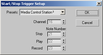
Start/Stop Trigger Setup dialog
- Presets
-
Choose the type of MIDI device. If you choose Media Control Station 2, you can use its buttons to Stop, Play, and Record.
(The Media Control Station is a MIDI device containing standard VCR-style playback buttons along with a jog wheel.) By choosing
Custom, you enable the remaining spinners in the dialog, where you can set specific channels and note numbers. You can also
use Custom to customize the controls used by the Media Control Station.
- Channel
-
Specifies the channel to which your MIDI device is assigned.
- Note Number
-
The Stop, Play, and Record spinners that follow this label let you specify which note event triggers which function.
- This note event stops the playback or the recording. On the Media Control Station, this would be the square button. This is
the equivalent of clicking the Stop button under the Record Controls group.
- Plays the animation. This is the arrow button on the Media Control Station.
- When this note is sent by itself, it's the equivalent of clicking the Test button under Record Controls. To record the motion
capture, you must press both Play and Record at the same time (the equivalent of clicking the Start button under Record Controls).
You can press the Play button before or after the Record button and release the Play button before or after the Record button.
The recording starts when the button is released.
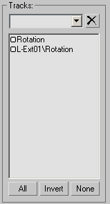
Tracks group
The Tracks area displays all tracks that have been assigned Motion Capture controllers. You select the tracks that will be
affected by the three buttons in the Record Controls group. Click a track to toggle its selection box on or off. Only the
selected tracks displaying the red box are affected by the Record Controls group.
You can select the tracks either by clicking them, or by using the All, Invert, None buttons. In addition, you can create
named selection sets of tracks. To create a named selection, click the tracks you want, and then enter a name in the Edit
field above the track list. To select a previously named set, open the Edit window, and select it from the list. To delete
a named set, select it from the list, and then click the Delete button at the right.
NoteA specific track can be in only one named selection at a time.
- All
-
Assigns all tracks to the Record Controls group.
- Invert
-
When tracks are selected, assigns the unselected tracks to the Record Controls Area.
- None
-
Assigns none of the tracks to the Record Controls group.
By default, each track is provided a name consisting of the name of the object followed by a backslash and the name of the
parameter. For example, Sphere01\Angle is an Angle parameter applied to one of the modifiers assigned to a sphere. You can
rename the tracks in the Properties dialog, which you can access in Track View, or by double-clicking the track name in the
Motion Capture utility. The upper rollout of each Properties dialog includes a Track Name field. Any name entered in the Track
Name field appears in the Track list in the command panel, in the title bar of the Properties dialog, and beside the Data
track in the Hierarchy list in Track View.
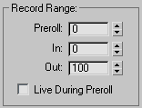
Record Range group
Specifies the frame range affected by the recording. You can also set a preroll range of frames (see below).
- Preroll
-
Specifies the frame number where the animation begins playing when you press the Start button. If this number is the same
or greater than the In number, the Preroll number is ignored. For example, if In: 0 and Out: 200, then a Preroll of -100 would
give you 100 frames before the recording started, while a Preroll of 50 would be meaningless. If the range defined by Preroll
and Out is larger than the current segment, the segment is temporarily enlarged during the recording.
- In
-
Specifies the frame number where the recording begins after you click Start.
- Out
-
Specifies the frame number where the recording ends after you click Start. You can stop the recording before this by clicking
Stop.
- Live During Preroll
-
When this is active, the motion capture is live through the preroll frames. The motion occurs, but isn't recorded. This can
cause sudden motion shifts at the In frame because your live motion might not match the animation when you reach the In frame.
When this option is inactive, the motion is disabled or frozen until you reach the In frame.
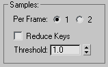
Samples group
When the motion data is captured, it’s sampled at a rate relative to the current frame rate, which defaults to 30 frames per
second. Increasing the frame rate increases the sample rate. The two radio buttons in this section allow you to choose one
or two samples per frame. This is a shortcut that lets you sample at a field rate. If you're rendering to fields, you don't
need to capture at 60 frames per second. Controllers will interpolate between the samples.
- Reduce Keys
-
Reduces the keys generated by the motion capture.
- Threshold
-
The value you enter in the Threshold field constrains how 3ds Max changes the selected track. The difference between the new animation and the original animation, at any frame, will be less
than the threshold value.
Low threshold values closely match the original animation but may not greatly reduce the number of keys.
High threshold values produce the fewest keys but may not match the original animation with much accuracy.
NoteWhen Reduce Keys is active, there is additional calculation time after each completed recording.
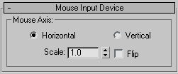
Mouse Input Device rollout
Controls animation using the horizontal or vertical motion of the mouse. The available settings include the following:
- Horizontal/Vertical
-
Specifies which mouse motion drives the animation.
- Scale
-
Scales the relative effect of the mouse movement to the animation response (Spinner Value: float, 0 to 999,999)
- Flip
-
Flips the direction of the response relative to the mouse movement. For example, if moving the mouse horizontally to the right
produces a clockwise effect on a Rotation controller. Activating Flip will reverse the rotation to counterclockwise.
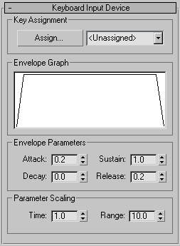
Keyboard Input Device rollout
Lets you assign most keyboard keys to drive the animation.
Key Assignment group
Click the Assign button, and then press any key. The assigned key appears in the list at right. Alternatively, you can open
the list and select a key from it.
- Assign
-
Click the Assign button, and then press any key. The assigned key appears in the lower list at right.
- Drop-Down List
-
You can open the list and select a key from it.
Envelope Graph group
Displays a representation of the amplitude curve over time.
Envelope Parameters group
Specifies the time over which the envelope of the action takes effect, relative to the key pressing and release.
- Attack
-
Displays the time it takes after pressing the key for the value to reach its maximum level.
- Decay
-
Displays the time it takes after having reached maximum for the value to fall to that specified by the Sustain spinner.
- Sustain
-
After the Attack and Decay, the value specified here is sustained until you release the key.
- Release
-
After releasing the key, this is the time it takes for the value to fade out to zero.
- Parameter Scaling Area
-
Sets the scale of the envelope and the range of the output value.
- Time
-
Specifies the scale of the Attack, Decay, and Release parameters. The value represents the number of seconds contained in
1 unit. For example, if this value is 1.0, then an Attack value of 1.0 equals 1 second.
- Range
-
Sets the maximum output value of the controller.
NoteThis controller ignores the state of the Ctrl, Alt, and Shift keys.
TipBecause a single keyboard key can only generate either a positive or negative value, if you want to control both directions
of a Bend Angle, for example, use a List controller. First, make sure there's a standard controller (such as a Bezier controller)
assigned first in the list to maintain the center position. Then add two Keyboard Motion Capture controllers to the list (one
assigned to one key, and the other assigned to a different key.) Set the range of one to the positive extent and the range
of the other to the negative extent.
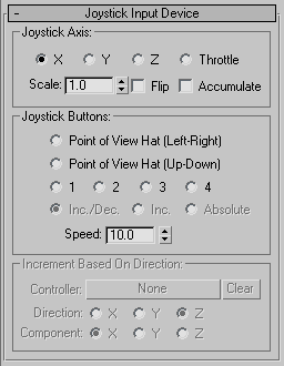
Joystick Input Device rollout
The Joystick Input Device driver was designed for the Microsoft Sidewinder joystick, which contains more controls than the
standard joystick. You can use this device driver for standard joysticks as well.
Joystick Axis group
- X, Y, Z
-
Specifies which joystick direction drives the animation. (Standard joysticks provide X and Y axes only. The Sidewinder provides
the Z axis when you twist the joystick.)
- Throttle
-
On the Sidewinder, this is a slider next to the stick.
- Scale
-
Scales the relative effect of the joystick action to the animation response (Spinner Value: float, 0 to 999,999)
- Flip
-
Flips the direction of the response.
- Accumulate
-
When turned off, the joystick position represents an absolute position, and you're limited to the "rectangle" defined by the
limits of the joystick. When the joystick returns to its rest position, the value generated returns to zero. When this is
turned on, the joystick represents a change in the current position. Moving the joystick forward, for example, can cause an
object to start moving, and it will continue to move until you return the joystick to its rest position.
Joystick Buttons group
- Point-of-View Hat (Left-Right, Up-Down)
-
The Sidewinder includes a mini-joystick on the tip of the main joystick. Specify the direction this joystick controls in the
animation.
- 1, 2, 3, 4
-
Specifies one of four buttons in the Sidewinder joystick. They work similarly to the Point-of-View Hat, except that each button
increases a direction value only while pressed. When you release the button, the value returns to zero (centered).
- Inc./Dec.
-
One of three options available only when you choose one of the numbered joystick button options. This option (Increment/Decrement)
means that the value is incremented when the button is down, and decremented when the button is up.
- Inc.
-
When turned on, the value increments when the button is down, and stays at that value when you release the button.
- Absolute
-
When turned on, the assigned parameters jumps to the value set in the Speed spinner when the button is down, and then jumps
back to zero when you release the button. Use this for on/off animations, such as blinking lights.
- Speed
-
Controls the rate at which the value changes when using either the Point-of-View Hat or the four buttons. When using a button
option and the Absolute option, this specifies the value output when you press the button (Spinner Value: float, -999,999
to 999,999).
Increment Based On Direction group
Provides controls that let you derive the direction of movement from a Rotation controller. These options are used primarily
when you're animating a first-person flythrough (such as when controlling a camera).
NoteThe items in this area are only available when you select Accumulate in Joystick Axis.
- Controller
-
Assigns a Rotation controller from which the direction will be derived.
- Clear
-
Removes the assigned controller.
- Direction X/Y/Z
-
Specifies the local axis that will be used as the direction. For a Free Camera, for example, this would be Z because the camera
points in the Z direction. However, if you had a car that pointed along its Y axis, you'd use Y.
- Component X/Y/Z
-
Specifies the edit binding to use. Match this to the Edit Binding button under Device Bindings. For example, if the Y Edit
Binding button is selected, choose the Y Component option.
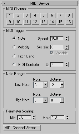
MIDI Device rollout
Controls animation using a MIDI device.
MIDI Channel group
Contains 16 buttons. Click to specify the channel to which your MIDI device is assigned.
MIDI Trigger group
Defines the type of MIDI event (message) that will drive the motion. There are four options.
NoteWhen you choose this option, the note number or pitch defines the output value. The value is derived from where the note falls
within the Note Range, specified in the Note Range group. When the note is at the bottom of the range, the value takes on
the Min value specified under Parameter Scaling. When the note is at the top of the range, the value takes on the Max value
from the same area. Anything in between is interpolated between the Min and Max values. (Note that Min doesn't have to be
less than Max.) The generated value will slide around as different keys are pressed. The harder a key is pressed, the faster
the value changes. The Speed setting defines how fast, overall, the value changes as keys are pressed.
- Velocity
-
When you choose this option, the velocity of the note pressed determines the output value. The notes set under Note Range
merely specify which notes are valid to press. The value takes on the Min value until a key within the Note Range is pressed.
When the key is pressed, the value approaches the Max value based on how hard the key was pressed. (The value actually travels
along a parabola toward the Max value.) The Sustain setting defines how long it takes the value to move through the parabola.
When you choose Variable, the sustain length is also scaled by how hard the key was pressed.
- Pitch Bend
-
The MIDI instrument's pitch bend knob defines the value. The Note Range doesn't apply in this case and is disabled.
- MIDI Controller
-
Specifies a note event when you're hooked up to a different type of MIDI controller than the typical keyboard. For example,
if you're using a MIDI slider box, you would select the MIDI Controller option, and then use the # spinner to specify the
note event for the specify slider.
Note Range group
- Low Note/High Note
-
Set these to specify the low and high ends of the note range when the Note option under MIDI Trigger is turned on.
Parameter Scaling group
Contains the Min and Max spinners, which specify the range of generated values. See Note and Velocity.
MIDI Channel Viewer
Clicking MIDI Channel Viewer at the bottom of the MIDI Device rollout displays a dialog that lets you test your MIDI device
to see which MIDI channel is receiving events, and which notes are being triggered.
MIDI Channel group
Provides a column of 16 buttons and progress bars representing the 16 MIDI channels. Select the channel from which you want
to view note activity. The channel progress bars light up when any channel has an event.
MIDI Note group
The 11 Octave buttons let you select which octave you want to view. When a note is played in that octave, a corresponding
progress bar lights up in the Note column.
- MIDI Controller #
-
When using a different type of MIDI controller, such as a slider box, you can specify a note event, and then watch the corresponding
progress bar light up when you activate that event. You can find the correct note number by activating the event while watching
the Note Number field at the bottom of the dialog.
- Channel
-
This is one of four text fields that display all of the values being generated by the MIDI device as you activate an event.
The Channel field displays the currently selected channel.
- Event
-
Displays the type of MIDI event being sent. This can be:
Note On: 9
Note Off: 8
Pitch Bend: 14
MIDI Controller: 11
- Velocity
-
Displays the velocity, which has a different meaning, depending on the event. For the most common event, a note being pressed,
this value represents the velocity at which the key was struck. Other events, however, might generate a continuous value.
For example, a pitch bend event transmits the position of the pitch bend.
- Note Number
-
Displays the corresponding note number for the event. When you're using a non-keyboard MIDI device, such as a slider box,
you can use this to identify the note number of a specific slider, for example.