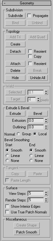
The Geometry rollout for patch objects contains most of the controls that let you alter the geometry of the patch, at either the Object (top) level, or one of the sub-object levels. The controls on the rollout vary, depending on which level is active; if a control is not available for the active level, it might be grayed out, or simply might not appear at all. The descriptions below indicate the levels at which controls are available.
Subdivision group (Vertex, Edge, Patch, and Element levels only)
Lets you create a seamless, gapless connection between two patch edges that have unequal numbers of vertices. The two patches must belong to the same object, and the vertex need not be selected first. Click Bind, then drag a line from an edge-based vertex (not a corner vertex) to the edge you want to bind it to. The cursor turns into a white cross when over a legal edge.
Binding patch edges
To exit Bind mode, click the Bind button again, or right-click in the active viewport.
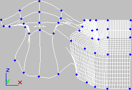
You can add Tri and Quad patches to any open edge of an object. On closed objects such as spheres, you can delete one or more existing patches to create open edges, and then add new patches.
The new patches adapt to the existing geometry. For example, when you add a patch to a curved edge, the new patch follows that curve and seamlessly extends it.
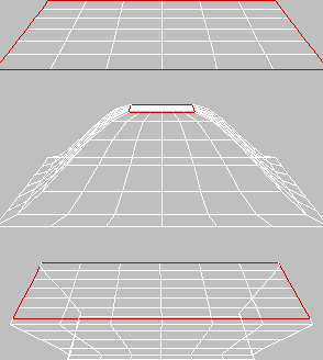
Original patch with edges selected (top) and three-sided patches added (bottom)
Add Tri adds a three-sided patch to each selected edge. Select one or more edges, then click Add Tri to add the patch or patches.
Add Quad adds a four-sided patch to each selected edge. Select one or more edges, and then click Add Quad to add the patch or patches.
Lets you add geometry to the patch object. Available at Vertex, Patch, and Element sub-object levels only.
At the Vertex sub-object level, turn on Create and then click anywhere to add vertices to the object.
At the Patch and Element levels, you can add three- and four-sided patches. The cursor changes to white cross hairs when over an existing patch vertex. Select an existing vertex by clicking it. Click in free space to create a new vertex at that location; this vertex is included in the sequence of vertices for the new patch.
No operation takes place if you right-click or select a vertex in the current sequence with only one or two vertices in the sequence.
Lets you select one or more patches or elements within the current object and then detach them (or copy them) to form a separate patch object.
Lets you attach an object to the currently selected patch object. Click the object you want to attach to the currently selected patch object.
If you attach a non-patch object, the object is converted to a patch object.
When you attach an object, the materials of the two objects are combined in the following way:
Attach remains active in all sub-object modes, but always applies to objects.
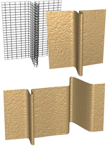
Top: Original patch object with rendering
Bottom: Rendering with another patch attached
For vertices, breaks a vertex into multiple vertices. Use this if you need to split open an edge to add another patch or for general modeling operations. Select a vertex, and then click Break. After the break, select the individual vertices and move them to separate the edges.
For edges, splits an edge. Use this if you need to split open an edge for general modeling operations. Select one or more edges, and then click Break. After the break, move the handles of adjacent vertices to create a gap in the patch.
Weld group (Vertex and Edge levels only)
Welds selected vertices that fall within the tolerance specified in the Weld Threshold spinner (to the right of the Weld button). Select the vertices you want to weld between two different patches, set the spinner to a sufficient distance, and click Selected.
At the Edge sub-object level, clicking Selected welds two edges that share vertices. You can use this to eliminate gaps on a surface.
Extrude & Bevel group (Edge, Patch, and Element levels only)
These controls let you extrude and bevel edges, patches, or elements. Extruding patches moves them along a normal and creates new patches that form the sides of the extrusion, connecting the selection to the object. Beveling adds a second step that lets you scale the extruded patches. You can extrude and bevel patches by dragging or by direct entry. You can also hold down the Shift key during extrusion, which creates a separate element.
Click this button, and then drag any patch or element to extrude it interactively, then click and release the mouse button, and drag again to bevel the extrusion. Hold down the Shift key during this operation to create a new element.
When the mouse cursor is over a selected element, it changes to a Bevel cursor.
Original patch (top) and inward and outward extrusions
If Normal is set to Local (the default), extrusion takes place along the normal of each selected edge, patch, or individual patch in an element. If normal is set to Group, extrusion takes place along the averaged normal of each contiguous group in a selection. If you extrude multiples of such groups, each group moves along its own averaged normal.
These settings let you set the shape of the intersection between the surface created by a beveling operation and the neighboring patches. The shapes are determined by the handle configurations of vertices at the intersections. Start refers to the intersection between the sides and the patches surrounding the beveled patch. Finish refers to the intersection between the sides and the beveled patch or patches. The following settings are available for each:
Tangent group (Vertex and Handle levels only)
These controls let you copy orientation, and optionally length, between handles on the same object, or on different objects applied with instances of the same Edit Patch modifier. The tool doesn't support copying handles from one patch object to another, or between spline and patch objects.
Copies a patch handle's transform settings to a copy buffer.
When you click Copy, 3ds Max displays all handles on the selected object. When the mouse cursor is over a handle end, the cursor image changes to the one shown below. Click a handle end to copy its direction and length to the paste buffer; this also exits Copy mode.

Pastes orientation information from the copy buffer to a vertex handle. If Paste Length is on, it also pastes the length of the copied handle.
When you click Paste, 3ds Max displays all handles on the selected object. When the mouse cursor is over a handle end, the cursor image changes to the one shown below. Click a handle end to paste the information from the buffer to the handle. You can continue clicking other handle ends to paste the information repeatedly. To exit Paste mode, right-click in the viewport or click the Paste button.

Determines how 3ds Max smoothes the edges between patches. Default=off.
When the check box is off, 3ds Max computes the surface normals from the smoothing groups of the mesh object to which the patch object is converted before rendering. These normals are not accurate, especially with a low View/Render Steps setting. When the check box is on, 3ds Max computes true patch normals directly from the patch surfaces, which can generate more accurate shading.
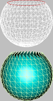
In the illustration below, a sphere was converted to Editable Patch format, and then a vertex was moved toward the center and rotated. The sphere on the left has Use True Patch Normals turned off, and the one on the right has it turned on. In both cases, View Steps was set to 8.
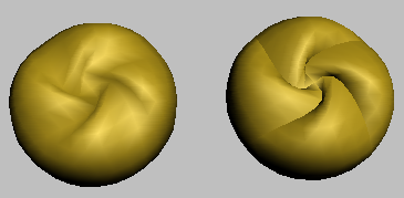
A patch sphere with Use True Patch Normals off (left) and on (right).
Creates splines based on the selected edges. If no edges are selected, then splines are created for all the patch edges. 3ds Max prompts you for a name: Type in a name for the new shape object, and then click OK.
Each patch edge forms an individual spline. You can use this to create a spline cage based on patch edges. This is useful for spline modeling or working with surface tools.
At the sub-object level, adjusts the tangent handles of the vertices of selected sub-objects to smooth the surface of the patch object. At the object level, adjusts all tangent handles to smooth the surface.
Patch Smooth sets the handles to absolute positions based on the patch object geometry; repeated applications have no effect.
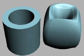
A patch tube before smoothing (left) and after using Patch Smooth (right)


 Modify panel