Command entry:
Select an object.


Modify panel
Modifier List
Optimize
Command entry:Select an object.
Modifiers menu
Mesh Editing
Optimize
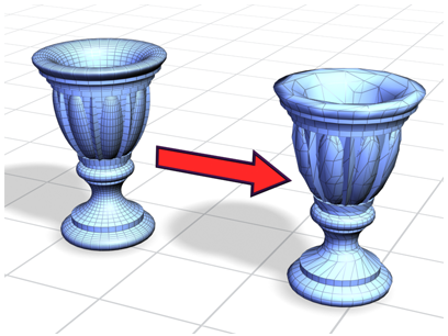
The Optimize modifier lets you reduce the number of faces and vertices in an object. This simplifies the geometry and speeds
up rendering while maintaining an acceptable image. A Before/After readout gives you exact feedback on the reduction as you
make each change.
TipBecause Optimize makes decisions based on angles between faces, it's sometimes best to apply it to selected face sub-objects
rather than to an entire object. Avoid applying Optimize to areas where you want to preserve geometric detail.
Applying Optimize
When you first apply Optimize, you might not see any change in the viewports. Adjust the Face Threshold setting to obtain
the best optimization. In the Last Optimize Status group, you can see how the object or faces were optimized. Watch these
values while you adjust the Optimize parameters, until you have the best possible result.
Setting Level of Detail
Optimize lets you maintain two levels of optimization detail. You might set a lower optimization level, with fewer faces,
to speed up your viewport work, and a higher level for final output in the renderer. However, you can render at either level.
You can also switch to the higher level in a viewport to get an idea of what the rendered image will look like.
Procedures
To optimize manually:
- Set up two viewports: one wireframe, one smooth shaded.
-
 Select an object and apply the Optimize modifier.
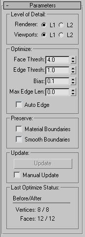
The Parameters rollout for this modifier appears.
- Turn off Manual Update and then adjust the Face Thresh value. Observe the result in the viewports.
You can also choose to view the results of the Optimize operation manually by leaving the Manual Update check box turned on
and clicking the Update button every time you wish to view a result.
- In the Parameters rollout Last Optimize Status group, notice the Before/After count for vertices and faces.
- In the Optimize group, vary parameters to continue reducing geometry.
Compare the result in the two viewports against the Before/After count.
To set the level of detail:
- In the Parameters rollout Level of Detail group, choose Viewports L1.
- Adjust parameters in the Optimize and Preserve groups.
This sets the L1 level of optimization for both the viewport and the renderer.
- Repeat steps 1 and 2 for Viewports L2, adjusting parameters for a different optimization.
To use level of detail:
The following parameters are stored for each level: Face Threshold, Edge Threshold, Bias, Max Edge Len, Material Boundaries,
and Smooth Boundaries.
Interface
Level of Detail group
- Renderer L1, L2
-
Set the level of display for the default scanline renderer. Use Viewports L1 and L2 to change the stored optimization level.
Default=L1.
- Viewports L1, L2
-
Set the optimization level for both viewport and renderer. Also toggles the level of display for the viewport. Default=L1.
Optimize group
Adjusts the degree of optimization.
- Face Thresh
-
Sets the threshold angle used to determine which faces are collapsed. Low values produce less optimization but better approximations
of the original shape. Higher values improve optimization, but are more likely to result in faces that render poorly (see
Bias). Default=4.0.
- Edge Thresh
-
Sets a different threshold angle for open edges (those that bound only one face). A low value preserves open edges. At the
same time you can apply a high face threshold to get good optimization. Default=1.0.
- Bias
-
Helps eliminate the skinny or degenerate triangles that occur during optimization, which can cause rendering artifacts. Higher
values keeps triangles from becoming degenerate. The default of 0.1 is enough to eliminate the skinniest triangles. Range=0.0
to 1.0 (a 0 value turns Bias off).
- Max Edge Len
-
Specifies the maximum length, beyond which an edge cannot be stretched when optimized. When Max Edge Len is 0, it has no effect.
Any value greater than 0 specifies the maximum length of the edges. Default=0.0.
Along with Bias, this control helps you avoid creating long skinny faces while optimizing.
- Auto Edge
-
Turns edges on and off following optimization. Turns on any open edges. Turns off any edges between faces whose normals are
within the face threshold; such edges beyond the threshold are not turned on. Default=off.
Preserve group
Maintains clean separation at the face level between material and smoothness boundaries.
- Material Boundaries
-
Prevents face collapse across material boundaries. Default=off.
- Smooth Boundaries
-
Optimizes an object and maintain its smoothing. When turned on, allows only faces that share at least one smoothing group
to collapse. Default=off.
Update group
- Update
-
Updates the viewports with the current optimization settings. Available only when Manual Update is turned on.
- Manual Update
-
Enables the Update button. When turned off, Optimize works as it does by default, updating the viewport display dynamically.
NoteWhen using Manual Update, if you make any changes that cause the reevaluation of the stack, the existing optimization display
disappears. Click the Update button again to restore it.
The Renderer ignores the optimization display in the viewport, using the Optimize settings, regardless of the state of the
Manual Update.
Last Optimize Status group
Displays numerical results of optimization with exact before-and-after counts for vertices and faces.