In this lesson, you use Revit to adjust some settings before enhancing the scene in 3ds Max Design.
To complete this lesson, you must have Revit installed on your workstation. If you do not have Revit installed, proceed directly to the next lesson, Linking a 3ds Max Design Scene to the FBX File.
 Open the Revit application. Click
  (Open). Navigate to the 3ds Max Design tutorial project folder
  \import\Revit_files. Highlight beachhouse.rvt and click Open.
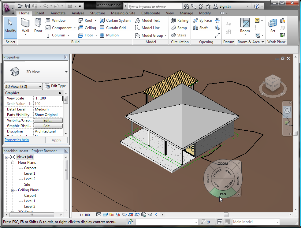
The beachhouse.rvt project features the model of a bungalow situated on a beach. In the procedure that follows, you will use options in Revit to change the model’s roof material, in preparation for exporting the scene.
Change the roof material in Revit:
 (Type Properties).
Type Parameters group Construction rollout Structure item, click Edit.
(Type Properties).
Type Parameters group Construction rollout Structure item, click Edit.
Revit displays a panel to the left, showing a detailed cross-section of the roof.
 Material column, click the top item in the list, Roofing - Asphalt.
After you click the Roofing - Asphalt entry, a  browser button appears. Click this button.


The texture and mapping coordinates of your selected material will be properly transferred to 3ds Max Design, with no further intervention required on your part.
Check light-object properties in Revit:
Like materials, all light-object properties in the Revit scene are accurately transferred to 3ds Max Design. Therefore, it is best to make sure that the lights you have in the current scene possess the properties you want to use in 3ds Max Design.
Ceiling Plans, double-click Level 1. 
 Zoom in to get a closer view of the ceiling plan for the main part of the house.
There are seven ceiling lights inside the house, and three outside on the porch.

Revit displays a description of the light object in the Properties panel to the left.

 Type Parameters group, scroll down to the Photometrics rollout and review the parameters displayed.
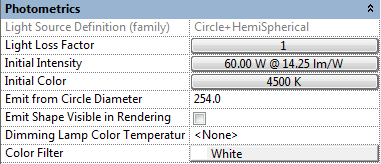
These values, particularly Initial Intensity and Color, will affect the rendered result in 3ds Max Design, so be sure these parameters contain the result you are looking for. (You can later update these values in 3ds Max Design, if you need to.)


By default, the 3D view in Revit uses an isometric perspective, but an FBX file must contain a single camera view: This view is the Revit camera that is active at the moment of export. Therefore, you must create at least one camera view in Revit before you export the scene. In this procedure, you create a camera for an exterior viewpoint.
Floor Plans and double-click Level 1.  Zoom so you have a view of the house and the area around it.
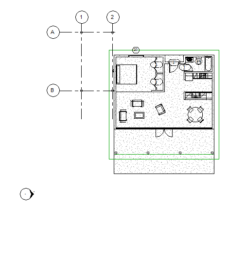
 3D View drop-down list, and choose Camera.

Revit creates a camera view. This is the view you will initially use to render your image in 3ds Max Design. It also changes the ribbon to show the Modify | Cameras tab.
 View Name field, change the name of the camera to Exterior, then click Apply (or press Enter).

After a pause, the view shows hills in the distance.
With Far Clip Active turned off, the camera is able to detect the scene terrain beyond the bungalow model. As with light and material properties, you can also modify clipping parameters in 3ds Max Design if you need to.

Camera view with clipping turned off, showing scene background
Set up rendering and the sun position:
 (Show Rendering Dialog).
Revit opens a Rendering dialog.

Most of the rendering values do not need to be changed, since the actual rendering of the scene will take place in 3ds Max Design. The Scheme setting in the Lighting group is one possible exception.
If you choose Exterior: Sun Only from the Lighting group Scheme drop-down list, then in the 3ds Max Design scene only the Daylight system will be turned on and all the man-made light objects will be turned off. Conversely, if you
choose Interior: Artificial Only, only the interior man-made light objects will be used in the scene and the Daylight system
will be turned off.
Sun Setting, click the  sun location button.
Revit opens a Sun Settings dialog, where you will set the geographic location and time of day for the position of the sun created by the daylight system.

(The Single Day and Multi-Day tabs let you choose presets that animate the position of the sun over the course of one or more days.)

Keep the default location of Boston, Massachusetts, because we imagine the house to be on Cape Cod, which is only slightly south of the city.
Date field, change the month to 5 and the day of the month to 10. 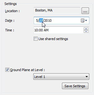


This name is appropriate because you want the Daylight system to show the actual sun position at Cape Cod in mid-afternoon.
The name of the preset now appears in the list in the Presets group.

 Close the Rendering dialog.
To export from Revit to the FBX format, you need to be in a 3D view, such as the Exterior camera view you have just created.
 Application menu and choose Export FBX.


