In this lesson, you will create two cylindrical objects, shape them using polygon edits, then use a union Boolean operation to add them to the Tower object.
 open \modeling\highrise\building2_tower_contour.max.
Change the size of the upper gap in the highrise:
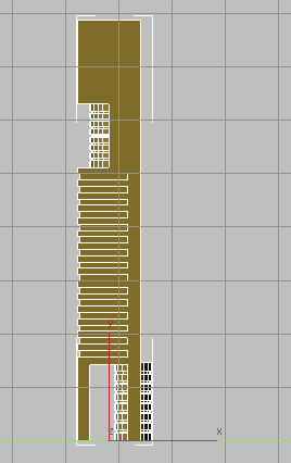
 Maximize the Perspective viewport and zoom in to the gap in the upper section of the tower, as shown in the illustration.
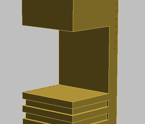
You will bring the back face of the Tower object forward to the midpoint of the structure. To accomplish this, you need to edit the operand that was used to expose the back face.
 Select the Tower object, and in the
  Modify panel
  Parameters rollout Display group, choose Operands.
This displays all the box objects, or operands, that were used to modify the Tower object.

 (Select And Move).
The box named Box17 (in building2_tower_contour.max) is the box that was used to make the topmost gap in the tower.
Repositioning the box to the midpoint of the tower involves a simple calculation: at a depth of 30 meters, the tower’s midpoint is 15 meters. Earlier, you offset the box from the back of the tower by six meters, so it needs to be repositioned to the left a further nine meters.
 relative units (X, Y, and Z spinners all display 0), then in the X field, type –9 , and press Enter.
3ds Max Design moves the box to the left by nine meters.
 Display group, turn on Result. The back face is now where you want it to be, at the midpoint of the tower.
The next step is to place a cylinder object in the gap between the floors. But rather than create this object at the ground plane as you did with all other objects in this tutorial, you will create this object directly on the upper platform.
Add the first cylinder to the building:
 Create panel, click
  (Geometry), then on the Object Type rollout, click Cylinder. Also, turn on AutoGrid.
With AutoGrid on, you can create the object on top of an object in the scene.

 (Align), then click the Tower object to display the Align Selection dialog.
This aligns the cylinder you just created to the center of the Tower object.
Modify panel Parameters rollout, set the parameters of the cylinder as follows: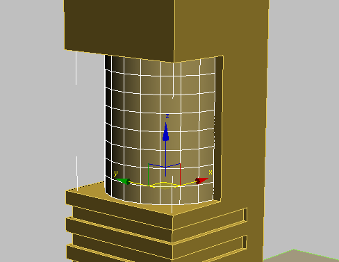
 (Select And Uniform Scale), and drag the X axis of the gizmo to the right. As you drag the gizmo, the X coordinate spinner
updates dynamically. When the spinner displays a value of 70, stop dragging.
(Select And Uniform Scale), and drag the X axis of the gizmo to the right. As you drag the gizmo, the X coordinate spinner
updates dynamically. When the spinner displays a value of 70, stop dragging.
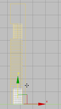
The cylinder shape should now resemble that shown in the next illustration.

Next, you will use some polygon editing techniques to add architectural detail to the cylinder object.
Detail the cylinder: Add windows:
 (Select Object).
Convert To Editable Poly.
(Select Object).
Convert To Editable Poly.
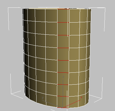
 (Edge), select any horizontal edge on the cylinder, then click the Ring button.
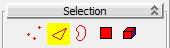
All horizontal edges above and below the selected edge are also selected.

 Settings button to the right of the Chamfer button.
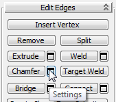
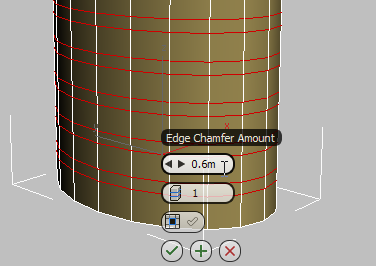
3ds Max Design displays the caddy controls for the Chamfer tool.
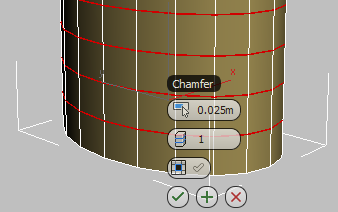
 (OK).
(OK).
3ds Max Design changes each horizontal edge loop into a pair of loops 0.6 meters apart.
Detail the cylinder: Bevel the windows:
 (Polygon).
 (Zoom Extents).
Hold down the Ctrl key, click just outside the cylinder object, and drag across each band created by the chamfer operation, as shown in the
next illustration.
(Zoom Extents).
Hold down the Ctrl key, click just outside the cylinder object, and drag across each band created by the chamfer operation, as shown in the
next illustration.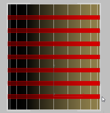 (Zoom Extents) again.
Settings button to the right of the Bevel button.
(Zoom Extents) again.
Settings button to the right of the Bevel button.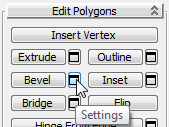
3ds Max Design displays the caddy controls for the Bevel tool.
 (OK).
(OK).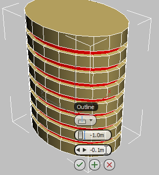
 (Polygon) to exit the Polygon sub-object level.
Place a copy of the cylinder at ground level, and position it:
(Select And Move).
 Object group, turn on Copy, then click OK.
This way, any changes you make to the newly copied object will not affect the upper cylinder.
 Absolute Mode and right-click the Z coordinates spinner arrows to position the object at ground level (0.0m).
 Move the cylinder to the right on its X axis, until it straddles the back portion of the Tower object, as shown in the next illustration.
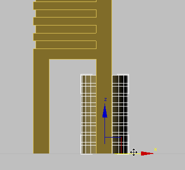
Scale the new cylinder, and merge the cylinders with the tower:
(Select And Uniform Scale) and drag the Y axis gizmo upward until the cylinder slightly penetrates the ceiling of the atrium
of the Tower object.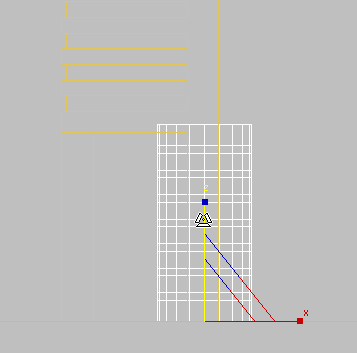 Select the Tower object. On the Modify panel Parameters rollout Operation group, choose Union.