The first time you start working with the render tree, it may be a little daunting. There are a lot of nodes and thousands of possible connections with more shaders than you know what to do with!
The trick to keeping focused is knowing what shader goes where and what it does. A good place to start is to know what can be plugged into the Material node, the Camera node, and the Light node.
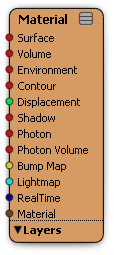
The Material node acts like a container for all of the possible shaders that can be applied to an object. Every object has a material node: without it, an object wouldn't render. Shaders can alter an object by invoking one or several of the shader input types.
| Input Type |
Function |
|---|---|
| Surface |
Determines the basic color of an object as well as the casting of reflected, refracted, and transparency rays. These usually use texture shaders to further define a material. See Working with Surface Shaders. |
| Volume |
Modifies rays as they pass through an object or the scene as a whole. It can simulate effects such as clouds, smoke, and fire. See Volume [Shader Reference]. |
| Environment |
Used instead of surface shaders when an eye ray leaves the scene entirely. It defines what is seen in the background or infinity. See Environment [Shader Reference]. |
| Contour |
Used to add contour effects to objects' edges, such as a cartoon effect shader. |
| Displacement |
Alters an object's surface by displacing its points; the resulting bumps are visibly raised and can cast shadows. Displacement is only visible in a rendering. See Displacement Maps [Texturing]. |
| Shadow |
Determines how the light coming from a light source is altered when it is obstructed by an object. It is used to define the way an object's shadow is cast, such as its opacity and color. |
| Photon |
Used for global illumination and caustic effects. Without this connection, an object could not receive or transmit photons. See Controlling the Photon Effect [Indirect Illumination]. |
| Photon Volume |
Used to define a volume for a photon effect. |
| Bump Map |
Determines how and where an object will display a bump map on its surface. See Creating a Bump Map in the Render Tree [Texturing]. |
| Lightmap |
Accepts connections from Lightmap shaders, which are used to sample object surfaces. |
| RealTime |
Accepts connections from realtime shaders. All other realtime rendered object attributes are set and adjusted in the realtime shader tree that connects to this port. See Realtime Shaders. |
| Material |
Accepts connections from a material phenomenon. Material phenomena are predefined combinations of shaders packaged as single nodes. For example, the Fast Subsurface Scattering shader is a material phenomenon. Note: Connecting a phenomenon to this input disables connections to all other material node inputs. |
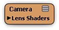
The Camera node acts like a container for all of the possible shaders that can be applied to a camera object. Every camera has a camera node to which you can connect a variety of lens shaders to its Lens Shaders port group.
| Input Type |
Function |
|---|---|
| Lens Shader |
Accepts connections from lens shaders. Lens shaders are used when a primary ray is cast by the camera. They may modify the ray's origin and direction to implement cameras other than the standard pinhole camera and they may modify the result of the primary ray to implement effects such as lens flares or a cartoon effect. See Applying Lens Shaders to Cameras. |
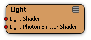
The Light node acts like a container for all of the possible shaders that can be applied to a light object. Every light has a light node to which you can connect a variety of light shaders to its input ports.
| Input Type |
Function |
|---|---|
| Light Shader |
Accepts connections from light shaders. Light shaders implement the characteristics of a light source. For example, a light shader uses the illumination direction to attenuate the amount of light emitted. A light shader is used whenever a surface shader uses a built-in function to evaluate a light. If shadows are used, light shaders normally cast shadow rays to detect obscuring objects between the light source and the illuminated point. See Light [Shader Reference]. |
| Light Photon Emitter Shader |
Accepts connections from photon-emitting light shaders. Instead of using an object's surface shader to calculate photon energy, you can make the light shader perform the necessary calculations by connecting to this port and using the light color as energy. See Using the Light Shader to Create Photons. |
Every node that appears in the render tree is color coded to identify it as a member of a particular shader family. A shader family indicates how a shader can be used in a render tree. Different shader families enforce different connection restrictions. For example, if a shader is from the light family, it can only be connected to a light node in the render tree.
As a render tree structure grows in size and complexity, color coding is very useful to locate a node's function at a glance. Here is the node color code:
|
Material phenomenon |
|
Surface Material and Shadow Material shaders |
|
Texture shader |
|
Lightmap shader |
|
Environment shader |
|
Realtime shader |
|
Volume Shader |
|
Output shader |
|
Lens shader |
|
Light and Photon Light shaders |
|
Photon Material and Photon Volume shaders |
|
Geometry shader |
|
Contour shader |
|
Image Clip shader. The standard image clip shader has the same node color as a writable image clip shader, but a different output port color to distinguish its particular function. For more information, see Image Clip Property Editor and Image Source Property Editor. |
|
Writable Image Clip shader. The writable image clip shader has the same node color as a standard image clip shader, but a different output port color to distinguish its particular function. For more information, see the Writable Image Source Property Editor. |
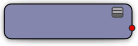
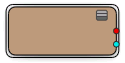
When a realtime effects shader fails to compile, it is displayed in the render tree as a bright red node to indicate that it's in an error state.

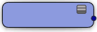
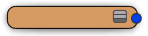
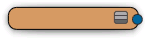
A shader compound contains multiple shaders grouped together into one node. The shader compound's node color has no real significance except to make it easier for you to identify it in a render tree. You can modify the shader compound's node color to suit your needs. However, the shader compound is distinguishable from a basic shader node because of its double-outline.
Every port (parameter) of every shader is color coded. A node's output ports are indicated by connection points (colored dots) on the right side of the node, and its input ports are indicated by connection points on the left side of the node. The color identifies what type of data the port will accept or output.
The following table describes the type of data each input or output port uses:
| Color |
Input/Output |
Result |
|---|---|---|

|
Color |
A color value expressed as a quadruple of scalars representing the RGBA channels. |

|
Scalar |
A real number represented as a decimal value, for example, 3.14. |

|
2D Vector |
A two-dimensional vector [x, y] whose entries are scalars, for example, a UV coordinate. |
|
|
3D Vector |
A three-dimensional vector [x, y, z] whose entries are scalars, for example, a surface normal. |

|
4D Vector |
A four-dimensional vector [w, x, y, z] whose entries are scalars. |

|
Boolean |
A Boolean value: True or False. |

|
Integer |
A positive or negative number without decimal fractions, for example, 7, –2, or 0. |

|
Image |
Accepts and outputs texture/image clip data. For more information, see Image Clip Property Editor and Image Source Property Editor. |

|
Image |
Accepts and outputs writable texture/image clip data. For example, this data type is accepted by the lightmap and depthmap input ports on a lightmap shader node. A writable image output port can also can be connected to a standard image input port. For more information, see the Writable Image Source Property Editor. |

|
RealTime |
Accepts and outputs realtime shader data. |

|
Lightmap |
Accepts and outputs lightmap shader data. For example, this data type is ouput by the ouput port on a lightmap shader node and accepted by the lightmap input port on the Material node. |

|
Material Phenomenon |
Accepts and outputs the result of a material phenomenon shader. |

|
3x3 Matrix |
A 3-by-3 matrix whose entries are real numbers. 3x3 matrices are often used to represent rotation and scaling. |

|
4x4 Matrix |
A 4-by-4 matrix whose entries are real numbers. 4x4 matrices are often used to represent transformations (scaling, rotation, and translation). |

|
Quaternion |
A quaternion [x, y, z, w]. Quaternions are usually used to represent an orientation. |

|
Reference |
A reference to an object, parameter, or attribute in the scene, expressed as a character string. |

|
String |
A string of characters. Strings can be used for storing file paths, for example. |

|
Custom |
Accepts a variety of data types. |
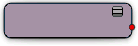
In the render tree, every shader node lists its parameters as ports. You connect shaders by plugging one node's output port into another node's input port, each of which represents a parameter.
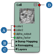
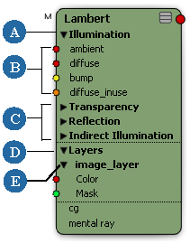
| A |
Shader input ports. |
| B |
Parameters that control related shader attributes are grouped into port groups. |
| C |
Texture layers are also grouped. |
| D |
Output port. |
As long as one node's output type matches the input type of the destination port, you can connect the two nodes. What happens depends on the value of the outputting node, the setting of the inputting node, and, of course, where you're connecting the node. For more information on how to connect shaders using the render tree, see Connecting Nodes.
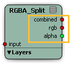
Some shader nodes have multiple output ports (also known as multi-output nodes). These nodes can extend the power of the render tree significantly, because the information calculated by the shader can be extracted to multiple data channels, and each channel can be used separately (with its own data type), instead of being combined into a single output. Multi-output nodes can serve several functions, such as the Particle Density shader that outputs both color and density at the same time to define the volume of a point cloud, or the RGBA Split shader that splits a texture's colors and alpha into separate outputs to be used elsewhere in the render tree, and so forth.
When a shader has a large number of parameters, their ports are grouped in the shader's render tree node. This is also true of texture layers that you add to a given node, each of which belongs to is own port group.
For information about collapsing and expanding port groups and texture layers, see Collapsing and Expanding Port Groups and Texture Layers.
For more information about connecting nodes to parameters in groups, see Inserting Nodes.
For more information about texture layers in the render tree, see Working with Texture Layers in the Render Tree.
Many shader nodes allow you to add input ports and port groups directly from the shader node in the render tree. You do not have to open the shader's property editor to access these controls. Although you will still have to open the property editor if you want to set static values, as opposed to driving the input values by other shaders. The workflow you choose is completely up to you.
In the render tree, dynamic ports and port groups can be created for lens shaders stacks, pass shaders stacks, texture layers, render channels (see the share shaders), and for a variety of input values (see the switch shaders).
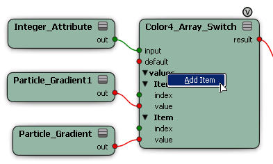
In the render tree workspace, set the shader node to its fully expanded state.
A port or another port group named "Item" is added to the shader node.
Right-click an input port and select a shader from the pop-up menu, or select More... to locate other shaders.
Repeat this task to add as many ports and shaders as you require for your effect.
To change the order of evaluation for a port or port group in the list, right-click it and select Move Up or Move Down.
To delete a port or port group from the list, right-click it and select Remove. Once a port is removed from the list, it no longer influences the effect.
 Except where otherwise noted, this work is licensed under a Creative Commons Attribution-NonCommercial-ShareAlike 3.0 Unported License


