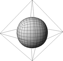
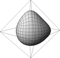
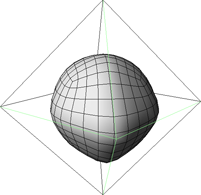
Subdivision surfaces typically produce a smooth result because the original vertex positions are averaged during the subdivision process. However, you can still create sharp spikes and creases in subdivision surfaces.
To create creases and spikes in subdivision surfaces, you select some points or edges on the hull and then choose Modify  Component Mark Hard Edge/Vertex to apply full hardness or Modify Component Set Edge/Vertex Crease Value to control the strength of the crease. You can also paint the crease values if desired.
You can select hard and crease edges or points using the Crease Edge or Crease Point selection filters available from the Filter menu button of the Select panel.
You can produce different types of creases, depending on whether you apply crease values to points or edges.
With edges, there are many possibilities for creating creases:
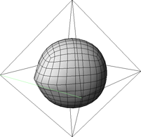
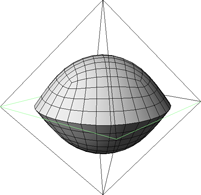
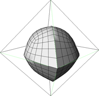
When you mark an edge or point as hard, you toggle its crease value to full. There is no gradation of values.
Setting Crease Values on Edges or Points
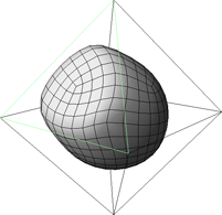
When you set a crease value on an edge or point, you can specify the amount. The effective range of the crease value is between 0 and the subdivision level.
To set crease values on edges or points
Select some points or edges on the control hull of the subdivision surface.
Choose Modify Component Set Edge/Vertex Crease Value. The Set Edge Crease Value property editor opens.
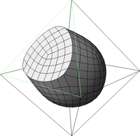
Adjust Crease Value to pull the subdivision surface toward the selected components. Values greater than the subdivision level of the surface have no effect.
You can connect the crease value to any kind of parameter map. In particular, you can paint on a weight map to modulate crease value as described below. For more information about mappable parameters in general, see Parameter Maps.
To paint crease values on points
Choose Get Property Weight Map.
If a cluster is selected, a weight map is created and applied to the cluster.
If points are selected, a cluster is automatically created and a weight map is applied to it.
If the object is selected, a cluster is automatically created containing all its points and a weight map is applied to the cluster.
The Weight Map property editor opens. You can leave the values at their defaults for now.
Re-select the polygon mesh, and select the edges or points on which you want to apply crease values.
Choose Modify Component Set Edge/Vertex Crease Value. The Set Edge Crease Value property editor opens.
Right-click the connection icon to the right of the Crease Value slider and choose Connect. Expand the node of the appropriate cluster and pick the weight map you created in step 3.
The Weight Map and Weight Map Generator pages are added to the property editor. Set the values as desired:
Crease Value is multiplied by the value from the weight map to give the crease value of a particular point. Crease Value must be greater than 0 to have any effect.
The value from the weight map ranges between the Minimum and the Maximum set on the Weight Map Generator page.
The Base Weight is the default, unpainted weight for each point in the weight map. It is expressed as a ratio between the Minimum and Maximum values.
Values higher than the subdivision level have no further effect.
Make sure that Use Weight Map is on in the Set Edge Crease Value page.
Activate the Paint tool by pressing W, then click and drag to paint in the 3D windows. In normal (additive) paint mode:
To remove weight, either use the right mouse button or press Shift while using the left mouse button.
To smooth weight values, press Alt while using the left mouse button.
To change the brush radius, press R while dragging with the left mouse button.
To change the opacity, press E while dragging with the left mouse button. The opacity controls the amount of weight added or removed with each brush stamp.
To change other brush properties, display the Brush Properties property editor by choosing Get Property Brush Properties or pressing Ctrl+W.
For more information about painting, see Using Brush-based Tools.