Verlet integration is an alternative to the Eulerian integration method used by the Simulate Particles node. While both methods have their advantages and disadvantages, one nice feature of Verlet integration is that it is easy to incorporate constraints, for example, to fix edge lengths, edge angles, and so on. This means that Verlet integration is often used for cloth and other soft-body simulations.
The supplied Verlet compounds are provided as examples to demonstrate how to set up and control Verlet simulations, and to form the basis of more complex effects.
Overview of Working with the Verlet Framework
Here is a high-level overview of the basic steps involved when simulating a mesh deformation using Verlet integration:
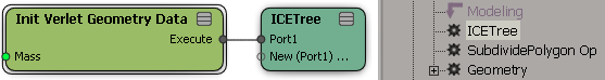
Create an unsimulated ICE node in the Modeling region of the mesh's construction stack above all topology modifiers, and connect an Init Verlet Geometry Data compound to store data for later use in the simulation.
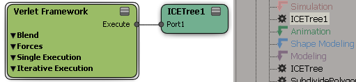
Create a simulated ICE tree and connect the Verlet Framework compound.
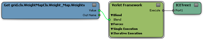
If desired, use the Blend parameter to control which points are simulated or not, for example, by connecting a weight map. Points with a value of 1 are simulated, points with a value of 0 are unsimulated, and the positions of points with values in-between 1 and 0 are interpolated between the simulated and unsimulated positions. For example, this lets you pin the corners of a cloth, or paint where you want fat to jiggle.
If desired, you can also specify the target to be used for the unsimulated points and for blending with the simulated points:
Use This Mesh Presimulate (0) uses the point positions stored by the Init Verlet Geometry Data compound.
Use Another Mesh (1) lets you specify another mesh to use as a target, such as an animated duplicate of the mesh. Note that you can get significant jittering at the first frame of the simulation if there is a large difference between the two meshes.
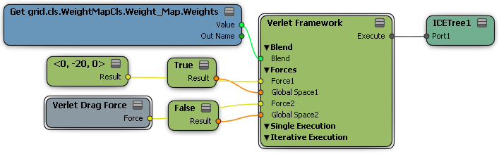
Add any forces desired. Every force has a toggle that controls whether it is applied in local or global space. You can use a simple 3D vector, such as a -Y value for gravity, or use any of the compounds from the Verlet Forces group of the Deformation task in the preset manager:
Connect any desired constraints into the Execute Each Iteration ports. To minimize jittering, decrease the weight of the constraints and increase the Iterations of the Verlet Framework compound. You can create your own constraints, or use one of the following compounds from the Verlet group in the preset manager:
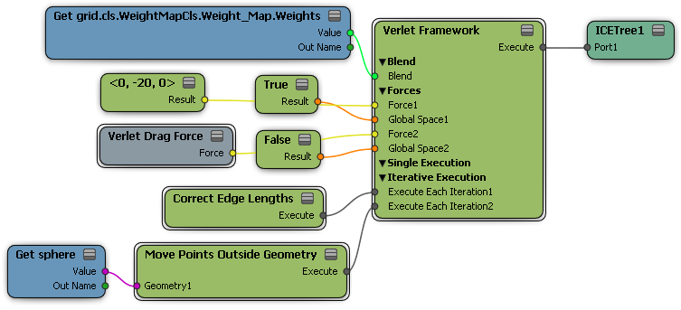
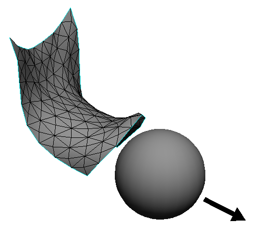
Here is an example of a very simple draping-cloth–like effect using the Verlet framework.
| A |
A weight map is used to pin the corners of the cloth. |
| B |
A simple gravity force is applied in local -Y. |
| C |
Verlet Drag Force prevents the mesh from bouncing around too much, and reduces its stretchiness. |
| D |
Under Iterative Execution:
These nodes are repeated several times each frame to obtain a more stable simulation. |
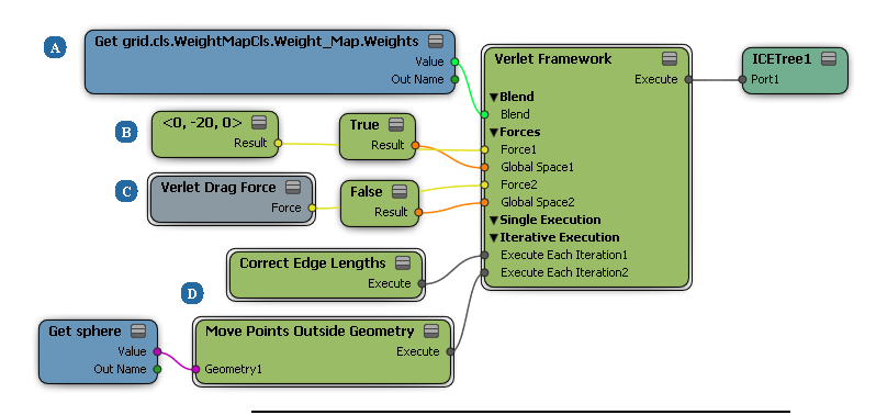
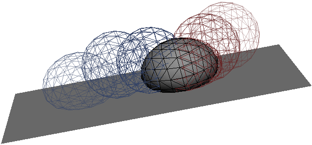
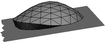
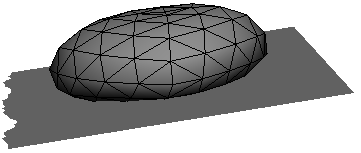
This example demonstrates a simple soft-body deformation using the Verlet Framework.
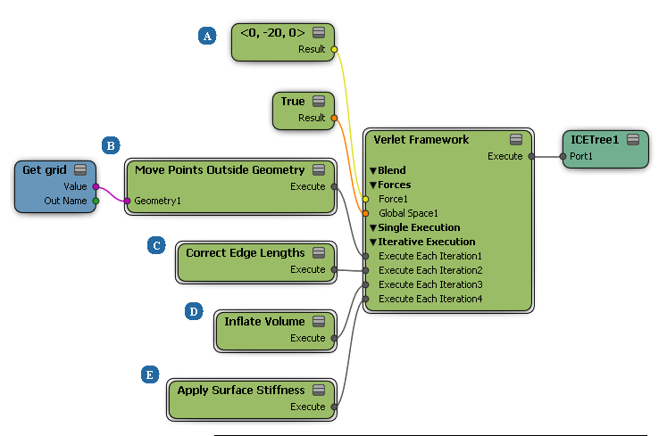
| A |
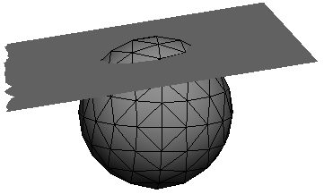
The 3D vector defines a gravity force that makes all points on the ball move downward. They fall right through the grid. |
|
| B |
Move Points Outside Geometry prevents the points from passing through the grid, but just leaves them flattened. |
|
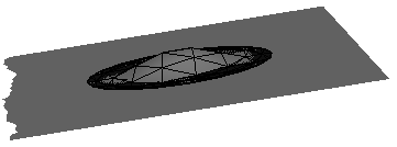
| C |
Correct Edge Lengths partially restores the original edge lengths, but the result is still crumpled. |
|
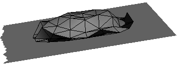
| D |
Inflate Volume partially restores the volume. |
|
| E |
Apply Surface Stiffness partially restores the original edge angles, smoothing out the sharp edges on the underside. |
|
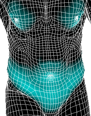
This example demonstrates how to paint jiggly fat on a character.
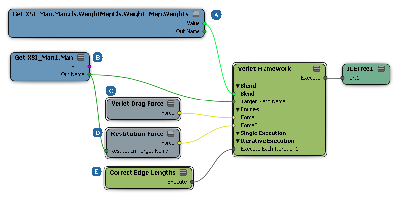
| A |
A weight map controls which points are affected by the simulation. |
| B |
The blend target is an animated duplicate of the mesh. A duplicate is required because the operators below the Simulation region are not re-evaluated during a simulation. |
| C |
Verlet Drag Force prevents excessive jiggliness. |
| D |
Restitution Force specifies a shape that points try to assume. In this case, it's the same animated duplicate that is used as the blend target. |
| E |
Correct Edge Lengths partially restores the original edge lengths, limiting the distance that the points can move. |


