You can measure the distance between two objects in the scene using the Ruler tool. When a measured distance is displayed, it is always displayed at the current camera view, enabling you to see the measured distance when working in Orthographic view (Producer Front, Producer Back, Producer Top, Producer Right, Producer Left, Producer Top, or Producer Bottom).
When you click the Ruler tool (  ) or use the Ruler keyboard shortcut Ctrl-Shift-R, the cursor changes to a 2D cursor (
  ).
).
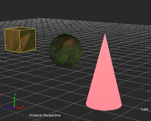
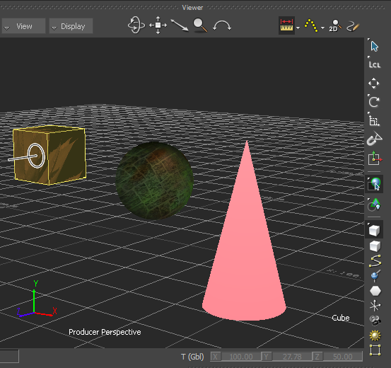
When you click the Ruler tool ( ) and hover over an object or element in the scene, the object is highlighted in yellow by default and the name of the object
is displayed at the bottom right of the Viewer window, as shown in the following figure.
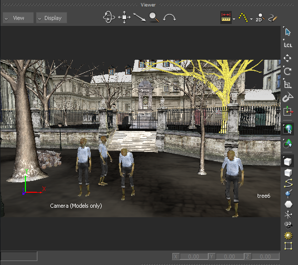
If you are working on a large scene, the highlighting of objects enables you to quickly identify and select in the scene the objects whose distance you want to measure.
When you click the Ruler tool ( ), hover over an object in the scene and click-hold the object, the cursor changes from a 2D cursor ( ) to a 3D cursor (  ) enabling you to snap to the surface of the object. Snapping a Ruler to the surface of an object gives you a visual feedback
on where you are snapping the object.
) enabling you to snap to the surface of the object. Snapping a Ruler to the surface of an object gives you a visual feedback
on where you are snapping the object.
When you click the Ruler tool ( ), hover over an element such as a light in the scene and click the light, the cursor changes from a 2D cursor ( ) to a 3D cursor ( ) enabling you to snap to the centre of the element. Unlike other elements, if you choose to snap a Ruler to a camera, the
Ruler snaps automatically to the camera film back—the camera's default rotation pivot.
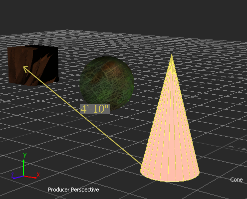
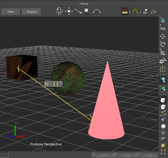
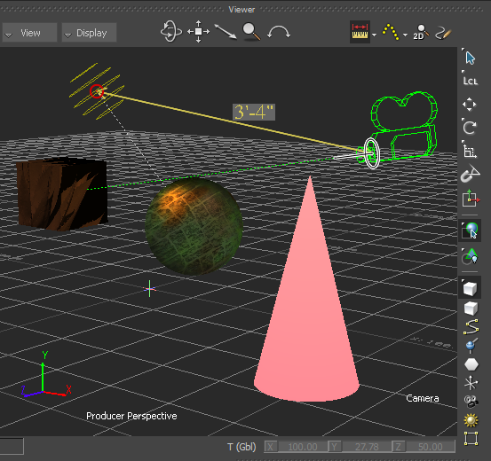
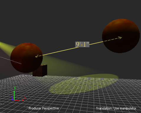
When you measure the distance between two objects or elements in the scene, the measured distance is displayed by default by a yellow line with arrows at the start and end points and the measurement units above the line. This measured distance is a system Ruler "object".
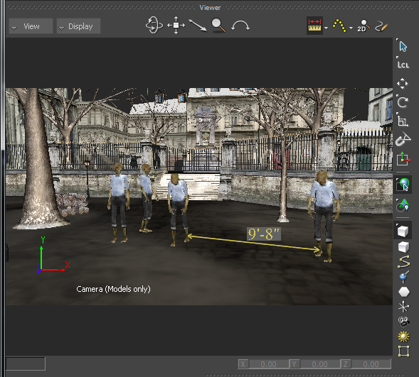
Ruler "object" displayed in the scene
The distance measurement units always face the current camera view, enabling you to see the measured distance irregardless of the camera view.
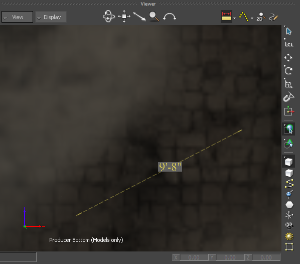
Measured distance facing the Orthographic Producer Bottom view
The distance measurement units are set by default in Architectural units to match the AutoCAD default measurement units. You can change the default Ruler settings via the Ruler preference settings.
See Changing the Ruler preferences.
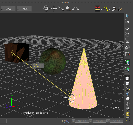
The system Ruler "object" is displayed in green when selected and the Viewer window indicates it is selected by displaying __MOBU_SYS_RULER_PATH__ at the bottom right, as shown in the following figure.
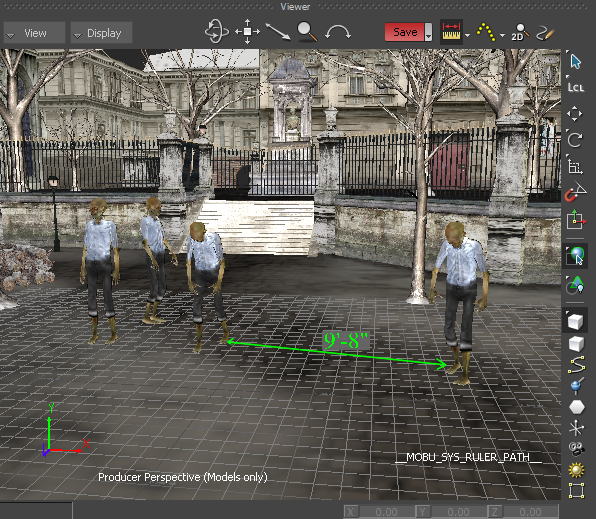
Ruler "object" shown selected
The system Ruler "object" is a system Ruler path. It is not an asset nor a model object. It has no properties and therefore is not available in the Asset browser, the Navigator Scene browser, and nor in the Schematic view.
You can toggle on or off the display of the system Ruler "object" in the scene by clicking the Ruler tool ( ). Depending on what the system Ruler "object" is snapped to, it is visible in Normal, X-Ray, Models Only and Models Display Wireframe display modes.
Although you cannot save the system Ruler "object" with the scene, you can save the measured distance between two objects or elements by converting the system Ruler "object" into a Dimension object.
You cannot undo an action when using the Ruler tool. You can however update the distance between two objects or elements by dragging either of the objects or elements. Standard path HUD elements are not displayed in the Viewer window when you are using the Ruler "object".
The Ruler tool ( ) enables you to draw a segment in the Viewer window.
The Ruler tool enables you to measure the distance between two objects or elements in a scene:
The Ruler tool ( ) enables you to view the measured distance update in real time as you translate the objects.
The Ruler remains snapped to non-deforming models because deformations are calculated on the GPU.
If you snap a Ruler onto an object that deforms in time, such as the dress or shirt of a model, the Ruler unsnaps. If you want the Ruler to remain snapped to a model, snap it to an object or element that does not deform in time such as a joint of a model as opposed to the dress or shirt of a model.
You can only have one Ruler in the scene. If you want to create another Ruler, you must first replace or delete the Ruler in the scene.
The Ruler tool ( ) enables you to save the measured distance between two objects or elements in a scene as a Dimension object.
See Saving the measured distance between two objects in the scene.
To measure the distance between two objects in a scene:
Setting the Display mode to Normal, X-Ray, Models Only, or Models Display Wireframe enables you to see objects and models, their bounding box centre (displayed as a Magenta hexagon), and their Rotation and Scaling pivots.
 ) in the Camera View Display toolbar options (
 ) (or press Ctrl-Shift-R).
The measuring distance displays and updates dynamically as you start to move the cursor.
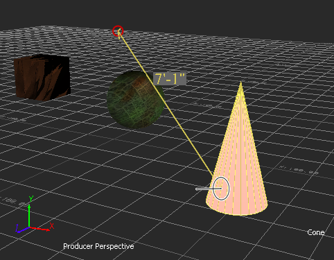
The system Ruler "object" is created and displays the distance between the two objects.
Ruler "object" displaying the distance between two objects
To measure the distance between two objects from their surfaces:
Setting the Display mode to Normal, X-Ray, Models Only, or Models Display Wireframe mode enables you to see objects and models, their bounding box centre (displayed as a Magenta hexagon), and their Rotation and Scaling pivots.
) in the Camera View Display toolbar options () (or press Ctrl-Shift-R).
) enabling you to snap to the surface of the object.
The 3D cursor is shown snapping to the surface of the cube.
The system Ruler "object" start point snaps to the surface of the object. The measuring distance displays and updates dynamically as you start to move the cursor.
The cursor changes to a 3D cursor ( ) enabling you to snap to the surface of the object.
3D cursor is shown snapping to the surface of the second object
The system Ruler "object" end point snaps to the surface of the second object and displays the distance between the two objects from their surfaces.
To measure the distance between elements in a scene:
Setting the Display mode to Normal, X-Ray, or Models Display Wireframe enables you to see objects and models, their bounding box centre (displayed as a Magenta hexagon), and their Rotation and Scaling pivots.
) in the Camera View Display toolbar (or press Ctrl-Shift-R).
The system Ruler "object" start point snaps to the center of the element.
The measuring distance displays and updates dynamically as you start to move the cursor.
Ruler "object" start point shown snapped to the center of the light
) over the camera.
The system Ruler "object" end point is automatically positioned at the centre of the camera film back regardless of where you position the cursor.
The position of the 3D cursor (  ) follows your cursor movement whereas the 3D cursor ( ) is automatically positioned by default at the centre of the camera film back—the camera's default Rotation pivot.
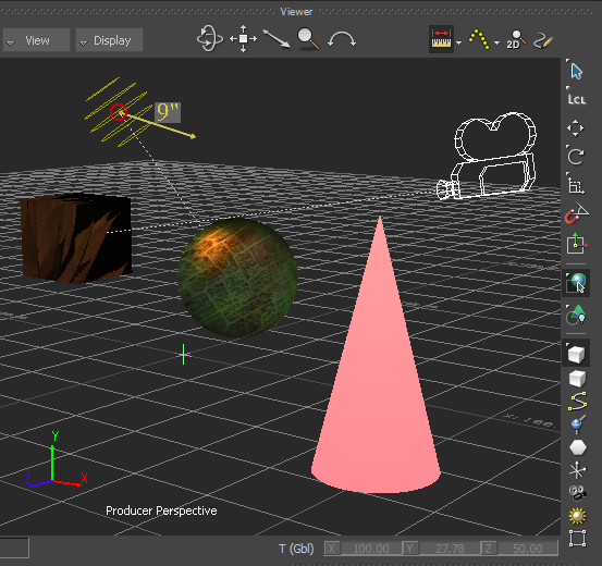
Distance measured from the centre point of a light to the centre point of the camera film back
The system Ruler "object" displays the distance between the centre point of the light and the centre point of the camera film back.
To measure the distance between a pivot offset of an object and the surface of another object:
Setting the Display mode to Normal, X-Ray, Models Only, or Models Display Wireframe mode enables you to see objects and models, their bounding box centre (displayed as a Magenta hexagon), and their Rotate and Scale pivots.
) in the Camera View Display toolbar (or press Ctrl-Shift-R).
The object is highlighted, and the object's bounding box centre (displayed as a Magenta hexagon) and the Rotate and Scale pivots are displayed, enabling you to snap to the bounding box centre of the object.
The system Ruler "object" start point snaps to object's pivot offset.
The measuring distance updates as you start to move the cursor.
The cursor changes to a 3D cursor ( ).
The system Ruler "object" end point snaps to the surface of the second object. The measured distance between the pivot offset of the first object and the surface of the second object is displayed.
To edit the distance between two objects:
 ) (or press T).
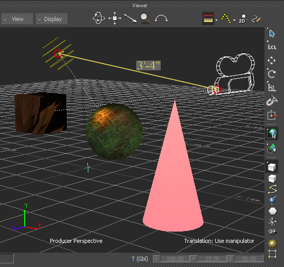
The system Ruler "object" remains snapped to the objects and the distance between the two objects updates dynamically.
The system Ruler "object" is shown as a dashed line when it is occluded, as seen in the following figure.
Ruler shown partially occluded
You can delete the Ruler via the Ruler tool ( ) arrow (context menu) or via the Ruler context menu in the scene. You can replace the Ruler via the Ruler tool context menu or by using the keyboard shortcut.
You can save with the scene the distance measured between two objects by converting the system Ruler "object" into a Dimension object.
 Except where otherwise noted, this work is licensed under a Creative Commons Attribution-NonCommercial-ShareAlike 3.0 Unported License


