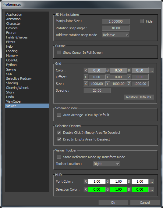
The Preferences window includes the Viewer preference settings.
To access the Viewer preferences:
The Viewer preference settings display.

The Viewer preference settings include the following settings:
The 3D Manipulators preference settings let you activate, disable, and change the appearance of the 3D Manipulators shown when objects are selected in the Viewer window. The following table describes the 3D Manipulator preference settings.
| 3D Manipulators settings | Purpose |
|---|---|
| Manipulator Size | Enter a value in this field to make the 3D manipulator handles/arrow appear larger or smaller in the Viewer window. |
| Hide | The Hide option lets you disable the display of the 3D manipulators. The default option is disabled so that the 3D manipulators are shown. |
| Rotation Snap Angle | The Rotation Snap Angle Field lets you specify an increment for the Snap Angle button to use when activated. To set a rotation increment, double-click the Rotation Snap Angle field and enter a value. See Setting a rotation increment. For information on using the Angle Snap button, see Snap Rotation. |
| Additive Rotation Snap Mode | Select Absolute from the menu to snap the rotation angle snap at exact increments, so, if you had set 10 in the Rotation Snap Angle field, the rotation would proceed incrementally 20, 30, 40, 50 degrees and so on. Select Relative to have the increments start relative to the position of the object. So, for example, if your object was at 12 degrees to begin with, and you specified a 10 degree angle, the rotation would be 22, 32, 42, 52, and so on. |
The Cursor preference setting enables you to set the default options for cursor actions in the MotionBuilder interface. The Show Cursor In Full Screen setting enables you to have the mouse pointer appear in full screen mode when activated and hide disabled.
The Grid preference settings lets you customize the grid displayed in the Viewer window. With the Grid options, you can set the color of grid lines, reposition the grid center, and alter the grid’s size and spacing. The following table describes the Grid preference settings.
| Grid settings | Purpose |
|---|---|
| Color | The Color values let you set the color of the grid lines. The main grid lines display a shade lighter to act as a guide. |
| Offset | The Offset values let you move the grid center from its default position. Only two components of this offset are used for each grid, for example, you can offset an “XZ” grid along the X and the Z axes, but not along the Y axis. |
| Size | The Size values let you set the size of the grids. For example, an XZ grid uses the X and Z coordinates of “Size” as its width and height. |
| Spacing | The Spacing value lets you set the distance between the grid lines. There is only one value necessary as the spacing is consistent for all dimensions. |
| Restore Defaults | Click the Restore Defaults button to return to the original grid options. |
The Schematic View preference setting contains the Auto Arrange On by Default option, which enables nodes to be automatically arranged in the Viewer (in the Schematic View). The setting is disabled by default.
The Selection Options preference settings let you configure the method used to deselect objects in the Viewer window. The following table describes the Selection Options preference settings.
| Selection Options settings | Purpose |
|---|---|
| Double Click in Empty Area to Deselect | Activate the Double Click in Empty Area to Deselect option if you want to deselect all selected objects by double-clicking in an empty area of the Viewer window. |
| Drag in Empty Area to Deselect | Activate the Drag in Empty Area to Deselect option if you want to deselect all selected objects by dragging in an empty area of the Viewer window. |
The Viewer Toolbar preference settings let you modify the toolbar position and set Transform reference modes. The following table describes the Viewer Toolbar preference settings.
| Viewer Toolbar settings | Purpose |
|---|---|
| Store Reference Mode By Transform Mode | Activate the Store Reference Mode By Transform Mode option if you want to set a Reference Mode (Local/Global/Additive) specific to each Transformation type. For example, you can set your Translations to be in Local mode, where your Rotations are set to Global. This way, when you switch back to Translating an object, the mode returns to Local automatically. |
| Toolbar Location | Select either Left or Right from the Toolbar Location menu to choose which side of the Viewer window the Viewer toolbar appears. |
The HUD (head-up display) preference settings let you change the color of commonly used visual feedback in the MotionBuilder user interface. The following table describes the HUD preference settings.
| HUD settings | Description |
|---|---|
| Font Color | Lets you change the color of the software operational statistics in the top-left corner of the Viewer window. See Display Rate. |
| Selection Color | Lets you change the color of the selected item visual feedback. |