In a new Maya scene, set the duration to 1000 frames and ensure it is set to playback at frame 1.
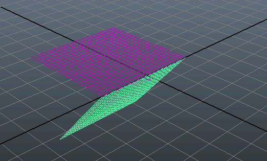
- Create two polygon meshes by selecting > > . When you create each plane, set the Width and Height to 5.
- Translate the meshes so that they meet along the Z axis. One way to do this is to set the X value of one mesh to 2.5 and the other value of one mesh to 2.5 and the other 0 -2.5.
- Select one mesh and convert it to a passive rigid body by selecting > . This is considered Rigid Body A.
- Select the other mesh and convert it to a active rigid body by selecting > . This is considered Rigid Body B.
- Select two meshes and select > to create a constraint between them.
- In the ( > ), select the bulletRigidBodyConstraint node.
- In the , click the bulletRigidBodyConstraintShape node tab.
- From the list, select . This creates a constraint between Rigid Body A and Rigid Body B along each object Z axis.
- Select Rigid Body B.
- In the , click the bulletRigidBodyShape node tab.
- In the section set to 0.4.
Play back the simulation. Rigid Body B swings back and forth along it Z axis. Over time, the rigid body swings decrease until
they stop at around frame 1000.
- To see the effects of enabling a Motor on the constraint, in the , select the bulletRigidBodyConstraint node.
- In the , in the Motors section, turn on .
Play back the simulation. Rigid Body B now swings at a constant speed in 360 degree rotations due to the Angular Motor.
 Except where otherwise noted, this work is licensed under a Creative Commons Attribution-NonCommercial-ShareAlike 3.0 Unported License